This thread has been locked.

If you have a related question, please click the "Ask a related question" button in the top right corner. The newly created question will be automatically linked to this question.

RTOS/TM4C1294NCPDT: PWM signal with lower-frequency

Part Number: TM4C1294NCPDT

Tool/software: TI-RTOS

Hi Everyone,

I am working on an application in which one task need to generate PWM signal with frequency ranging from 0.25Hz to 25Hz (Period value ranging from 40 to 4000 millisecond).
Following is my configuraion

1) PWM Hardware Attributes code snippet:

const PWMTiva_HWAttrs pwmTivaHWAttrs[EK_TM4C1294XL_PWMCOUNT] = {
    {
        .baseAddr = PWM0_BASE,
        .pwmOutput = PWM_OUT_0,
        .pwmGenOpts = PWM_GEN_MODE_DOWN | PWM_GEN_MODE_DBG_RUN
    },
    {
         .baseAddr = PWM0_BASE,
         .pwmOutput = PWM_OUT_1,
         .pwmGenOpts = PWM_GEN_MODE_DOWN | PWM_GEN_MODE_DBG_RUN
    },
    {
         .baseAddr = PWM0_BASE,
         .pwmOutput = PWM_OUT_2,
         .pwmGenOpts = PWM_GEN_MODE_DOWN | PWM_GEN_MODE_DBG_RUN
     },
};

const PWM_Config PWM_config[] = {
    {
        .fxnTablePtr = &PWMTiva_fxnTable,
        .object = &pwmTivaObjects[0],
        .hwAttrs = &pwmTivaHWAttrs[0]
    },
    {
         .fxnTablePtr = &PWMTiva_fxnTable,
         .object = &pwmTivaObjects[1],
         .hwAttrs = &pwmTivaHWAttrs[1]
    },
    {
         .fxnTablePtr = &PWMTiva_fxnTable,
         .object = &pwmTivaObjects[2],
         .hwAttrs = &pwmTivaHWAttrs[2]
    },
    {NULL, NULL, NULL}
};

2) PWM Pin Mux and GPIO configurations

void EK_TM4C1294XL_initPWM(void)
{
    /* Enable PWM module 0 */
    SysCtlPeripheralEnable(SYSCTL_PERIPH_PWM0);


    GPIOPinConfigure(GPIO_PF0_M0PWM0);
    GPIOPinTypePWM(GPIO_PORTF_BASE, GPIO_PIN_0);

    GPIOPinConfigure(GPIO_PF1_M0PWM1);
    GPIOPinTypePWM(GPIO_PORTF_BASE, GPIO_PIN_1);


    GPIOPinConfigure(GPIO_PF2_M0PWM2);
    GPIOPinTypePWM(GPIO_PORTF_BASE, GPIO_PIN_2);

    PWM_init();
}

3) EK_TM4C1294XL.h enum updating with three PWM outputs.

typedef enum EK_TM4C1294XL_PWMName {
    EK_TM4C1294XL_PWM0 = 0,
    EK_TM4C1294XL_PWM1,
    EK_TM4C1294XL_PWM2,

    EK_TM4C1294XL_PWMCOUNT //=3
} EK_TM4C1294XL_PWMName;

4) PWM Configuration parameters

Tried these two modes:

1) PWM duty mode: PWM_DUTY_TIME: Period and duty cycle value assigned in microseconds.

2) PWM duty mode: PWM_DUTY_SCALAR: Calculation:

duty_cycle_percentage = ((On_time * 1000) / ((On_time + Off_time) *1000)) * 100

duty_cycle_scalar = (65535 * Duty_cycle_percentage) / 100

PWM_setDuty(pwmHandle, duty_cycle_scalar);

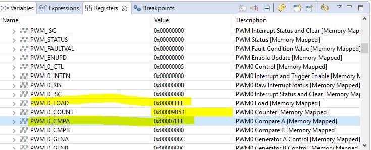
Problem: With Period value ranging from 40 to 68 milliseconds (Frequency 25Hz to 14.705Hz), I am able to generate PWM signal. But when I am trying for period value equal to 70 millisecond and above(Frequency 14.28Hz and below), PWM signal line becomes high and no change after that.

I wanted to know, Can PWM module generate this low frequency signal? If yes, what configurations do I need to do in TI-RTOS project to achieve this low frequency.

And PWM signal with 20 millisecond duty cycle, DSO shows value as 10ms duty cycle. I am not sure, why this is happening.

Any help will be really appreciated. Thanks in advance.

  • Hi,

      A couple things to check with you.

      - I assume you set the PMW_DUTY_SCALAR before you open the PWM driver instance. Is this correct? The default is PWM_DUTY_TIME. Once the driver instance is opened, the only way to change the operating mode is to close and re-open the instance with a new mode. Please see below from the user's guide. 

    The mode is determined by the PWM_DutyMode field within PWM_Params data structure. The
    PWM_Params default for this field is PWM_DUTY_TIME mode. Once opened, the only way to change
    the operating mode is to close and re-open the PWM instance with a new mode.

     - Can you check the PWMCC register in the register browser window and check what the PWM clock divider you have? The PWM module is based on the 16-bit counter. The fastest PWM clock can be 120MHz which is equal to the system clock.  If your PWM clock is equal to system clock (PWM clock is divide by 1 from system clock) then the maximum period you can have is 8.3ns * 65535 = 0.544ms. If the PWM clock is divided by 64 from system clock then the maximum period you can have is 34ms. 

  • Hi,

    Thanks for such super fast response. Yes, I am setting PWM duty mode before opening the PWM instance. Please find the piece of code below:

    PWM_Params pwm_params;

    PWM_Handle pwm1;

    PWM_Params_init(&pwm_params);
    pwm_params.dutyMode = PWM_DUTY_SCALAR;

    pwm_params.period = (ton + toff) * 1000; //Period in microsecond

    pwm1 = PWM_open(Board_PWM1, &pwm_params);
    if (pwm1 == NULL) {
         System_abort("Board_PWM1 did not open");
    }

    duty_cycle_percentage = ((ton * 1000) / pwm_params.period) * 100;

    duty_cycle = (65535 * duty_cycle_percentage) / 100;

    PWM_setDuty(pwm1, duty_cycle);

    In registers browser window, I found PWMCC register has value 0x00000005, So this indicates PWM clock is divided by 64 and that is why I am able to input maximum period as 34ms. 

    Can please help me with how can I change this register value to get clock division value to 1, to get frequency as 0.544ms?

  • Hi,

      Please note that to use the divider clock the bit 8 needs to be set to high. Please see below. If you have bit 8 low then it is using the source clock to the PWM module is the system clock. 

    The TI-RTOS as far as I know does not have an API to configure the PWM clock dynamically. I will suggest you use the TivaWare PWMClockSet() API to configure the divider. This API will set bit 8 and use the divider clock as the clock source.  

  • Hi Everyone,

    I used PWMClockSet() to change PWM clock configuration. But it has no effect. Can you please tell me where to add this particular line of code.

    I tried doing these:

    1) Inside the task where PWM module is configured to generate PWM signal. Here I called API PWMClockSet() before creating PWM handles. : This had no effect.

    PWM_Handle pwm1;

    PWMClockSet(PWM0_BASE, PWM_SYSCLK_DIV_1);

    PWM_Params pwm_params;
    PWM_Params_init(&pwm_params);

    pwm_params.dutyMode = PWM_DUTY_SCALAR;

    pwm_params.period = 200;

    pwm1 = PWM_open(Board_PWM1, &pwm_params);
    if (pwm1 == NULL) {
                System_abort("Board_PWM1 did not open");
    }

    2) In file EK_TM4C1294XL.c as shown below:

    void EK_TM4C1294XL_initPWM(void)
    {
        /* Enable PWM module 0 */
        SysCtlPeripheralEnable(SYSCTL_PERIPH_PWM0);
        PWMClockSet(PWM0_BASE, PWM_SYSCLK_DIV_1);

        GPIOPinConfigure(GPIO_PF0_M0PWM0);
        GPIOPinTypePWM(GPIO_PORTF_BASE, GPIO_PIN_0);

        GPIOPinConfigure(GPIO_PF1_M0PWM1);
        GPIOPinTypePWM(GPIO_PORTF_BASE, GPIO_PIN_1);

        GPIOPinConfigure(GPIO_PF2_M0PWM2);
        GPIOPinTypePWM(GPIO_PORTF_BASE, GPIO_PIN_2);

        PWM_init();
    }

    In both cases, I am not able to generate PWM signal above 34ms. Please provide some suggestions.

  • Hi,

      I have forwarded your question to our TI-RTOS experts. 

  • Hi,

      Can you try to call the PWMClockSet() after the PWM_open()?

  • Hi Charles,

    Thanks for response. But still there is no improvement. Whenever I am giving value greater than 34ms as on time/duty cycle. It is not working.

    One observation I have, if this helps to find the root cause of this, whenever I pass on time as 34ms and off time as 34ms (duty cycle is 50% and period value is 68ms(params.period= 68000)). PWM signal is generated. But in DSO, I see on time and off time as half of the input value.

    Please provide us guidance.


  • Hi,

      Can you please clarify that with the PWMClockSet() inserted, there is no effect at all or there is some change in behavior but just not correct behavior?

      When you view the PWMCC register do you see the new change?

  • Hi again,

      Wait a minute. In my earlier reply I said that with the PWM clock divided by 64 from system clock you will get a maximum period of 34mS due to the 16-bit counter width. At 120MHz the system clock cycle is 8.3ns. If the PWM clock is divided by 64 then the PWM clock period is 531ns. 531ns * 2^16 = 34.8ms. This means you can only get about 17.4ms of ON and 17.4ms of OFF times in a 50/50 duty cycle PWM. 

      You might want to explore using the GPTM module in the MCU. The GPTM module in the MCU can also operate in PWM mode and it can give you up to 24-bit of precision. Another solution is for you is to slow down the system clock frequency. If you operate at 60MHz or slower then it will give you the maximum period you want but running at slower system clock will also slow down your device performance. It will be a trade-off for you.

      Must you use RTOS in your application?

  • Hi,

    As you suggested, I used PWMClockSet() API after PWM_open(). After compiling and flashing, I checked the register value and it is 0x0.

    Three PWM outputs(PWM_OUT_0, PWM_OUT_1 and PWM_OUT_2) are configured. Now I am observing that whenever I am writing period value in microseconds(that is value above 34ms), I get something like this (for Board_PWM1 and it says "Couldn't open Board_PWM1"):

    Couldn't open Board_PWM. Current duty cycle is 32767
    FSR = 0x0000
    HFSR = 0x40000000
    DFSR = 0x0000000b
    MMAR = 0xe000ed34
    BFAR = 0xe000ed38
    AFSR = 0x00000000
    Terminating execution..

    I tried one more, that is tried changing PWM outputs from PWM_OUT_1 to PWM_OUT_2 and PWM_OUT_3 to PWM_OUT_4 in EK_TM4C1294XL.h file. Please find code snippet below. After doing this, program won't terminate but signal is high all the time.

    const PWMTiva_HWAttrs pwmTivaHWAttrs[EK_TM4C1294XL_PWMCOUNT] = {
        {
            .baseAddr = PWM0_BASE,
            .pwmOutput = PWM_OUT_0,
            .pwmGenOpts = PWM_GEN_MODE_DOWN | PWM_GEN_MODE_DBG_RUN
        },
        {
             .baseAddr = PWM0_BASE,
             .pwmOutput = PWM_OUT_2,
             .pwmGenOpts = PWM_GEN_MODE_DOWN | PWM_GEN_MODE_DBG_RUN
        },
        {
             .baseAddr = PWM0_BASE,
             .pwmOutput = PWM_OUT_4,
             .pwmGenOpts = PWM_GEN_MODE_DOWN | PWM_GEN_MODE_DBG_RUN
         },
    };

    Yes, our major requirement is to use TI-RTOS. Okay, we can use GPTM module if this gives positive results. But don't see any information/APIs related to GPTM module in TI-RTOS user guide. Can you suggest me where to find it?

    Can you also please explain me what will be values for period and duty cycle in case of PWM_DUTY_SCALAR mode? For example: I am having 20ms as On time and 20ms as Off time. So the period value becomes 40ms. Based on that I am supplying period parameter a value:

    pwm_params.period = period = (on_time + off_time) * 1000; // as period is in microseconds.

    duty_cycle is calculated using this formula:

    float duty_cycle_percentage;

    int32_t current_duty_cycle;

    duty_cycle_percentage = on_time * 1000;
    duty_cycle_percentage = duty_cycle_percentage / ((on_time + off_time) * 1000);
    current_duty_cycle = duty_cycle_percentage * 100;
    current_duty_cycle = (current_duty_cycle * 65535) / 100;

    Am I doing anything wrong here or is there any better way to calculate these values? As in Scope, for 20ms on time and 20ms off time, I see frequency as 50Hz but it should be 25Hz right?

  • Hi,

    I am glad that you are supporting us. Can you explain me what will be values for period and duty cycle in case of PWM_DUTY_SCALAR mode? For example: I am having 20ms as On time and 20ms as Off time. So the period value becomes 40ms. Based on that I am supplying period parameter a value:

    pwm_params.period = period = (on_time + off_time) * 1000; // as period is in microseconds.

    duty_cycle is calculated using this formula:

    float duty_cycle_percentage;

    int32_t current_duty_cycle;

    duty_cycle_percentage = on_time * 1000;
    duty_cycle_percentage = duty_cycle_percentage / ((on_time + off_time) * 1000);
    current_duty_cycle = duty_cycle_percentage * 100;
    current_duty_cycle = (current_duty_cycle * 65535) / 100;

    Am I doing anything wrong here or is there any better way to calculate these values? As in Scope, for 20ms on time and 20ms off time, I see frequency as 50Hz but it should be 25Hz right?

  • Hi Nishitha,

      Did you have a chance to read my last reply? As I explained the maximum period is limited by the PWM module being a 16-bit counter. The maximum period will be about 35ms (or more precisely 34.952ms) which is equal to 28.57Hz. You cannot get any lower than that. Therefore, 25Hz is not achievable. When you specify 40ms as the period, you overflow what the 16-bit counter is able to support. Some incorrect preload value is loaded to the PWM0_LOAD register. Check the register in the register window and you will know what I meant. 

    Below is an experiment I just did. I configure the PWM to have a maximum period of 34.952ms. 

    Void pwmLEDFxn(UArg arg0, UArg arg1)
    {
        PWM_Handle pwm1;
        PWM_Params params;
        uint16_t   pwmPeriod = 34952;      // the maximum PWM period a 16-bit counter can support is 34.952ms
        uint16_t   duty = 32768;           // 32768 is 50% of 65535
    
        PWM_Params_init(&params);
        params.period = pwmPeriod;
        params.dutyMode = PWM_DUTY_SCALAR;
    
    
        pwm1 = PWM_open(Board_PWM0, &params);
    
        if (pwm1 == NULL) {
            System_abort("Board_PWM0 did not open");
        }
    
        /* Loop forever incrementing the PWM duty */
        while (1) {
            PWM_setDuty(pwm1, duty);
    
            Task_sleep((UInt) arg0);
        }
    }

    If you look at the PWM_0_LOAD register the value got loaded is 0xFFFE which is close to the maximum value a 16-bit register can hold. Look at the PWM_0_CMPA which determines the duty cycle is half of the period. 

  • Hi Charles,

    Thanks for that explaination. This makes sense, even I had observed 0x0000FFFF in load register.

    As you suggested to use GPTM module, how can I get this working? I couldn't find any APIs in TI RTOS user guide? Please suggest me on this.

    If you have any other ideas to fix this please let me know.

  • Hi,

      TI-RTOS doesn't have API to support Timer module operating in PWM mode. You will need to use TivaWare to accomplish. First please refer to the datasheet to understand how the GPTM module works and capable of operating in PWM mode. You can then refer to the TivaWare example <TivaWare_Installation>/examples/peripherals/timer/pwm.c. Run the example as is to get a feel of it before you migrate the code to TI-RTOS. Please also be aware of the fact that the BIOS borrows two timers from the hardware to manage the BIOS system tick and timestamp provider. Normally it is using the first two timers in the system. If you still want to use the TI-RTOS provided driver for PWM then the best recommendation I have is slow down the system clock. For example, if you configure the system clock to 60MHz then you will be able to use the 16-bit PWM module to get the desired 40ms period.

    I have also modified the the example a little bit to get close to 40ms of PWM period.


    //*****************************************************************************
    //
    // pwm.c - Example demonstrating timer-based PWM on a 16-bit CCP.
    //
    // Copyright (c) 2010-2017 Texas Instruments Incorporated.  All rights reserved.
    // Software License Agreement
    // 
    //   Redistribution and use in source and binary forms, with or without
    //   modification, are permitted provided that the following conditions
    //   are met:
    //
    //   Redistributions of source code must retain the above copyright
    //   notice, this list of conditions and the following disclaimer.
    //
    //   Redistributions in binary form must reproduce the above copyright
    //   notice, this list of conditions and the following disclaimer in the
    //   documentation and/or other materials provided with the
    //   distribution.
    //
    //   Neither the name of Texas Instruments Incorporated nor the names of
    //   its contributors may be used to endorse or promote products derived
    //   from this software without specific prior written permission.
    // 
    // THIS SOFTWARE IS PROVIDED BY THE COPYRIGHT HOLDERS AND CONTRIBUTORS
    // "AS IS" AND ANY EXPRESS OR IMPLIED WARRANTIES, INCLUDING, BUT NOT
    // LIMITED TO, THE IMPLIED WARRANTIES OF MERCHANTABILITY AND FITNESS FOR
    // A PARTICULAR PURPOSE ARE DISCLAIMED. IN NO EVENT SHALL THE COPYRIGHT
    // OWNER OR CONTRIBUTORS BE LIABLE FOR ANY DIRECT, INDIRECT, INCIDENTAL,
    // SPECIAL, EXEMPLARY, OR CONSEQUENTIAL DAMAGES (INCLUDING, BUT NOT
    // LIMITED TO, PROCUREMENT OF SUBSTITUTE GOODS OR SERVICES; LOSS OF USE,
    // DATA, OR PROFITS; OR BUSINESS INTERRUPTION) HOWEVER CAUSED AND ON ANY
    // THEORY OF LIABILITY, WHETHER IN CONTRACT, STRICT LIABILITY, OR TORT
    // (INCLUDING NEGLIGENCE OR OTHERWISE) ARISING IN ANY WAY OUT OF THE USE
    // OF THIS SOFTWARE, EVEN IF ADVISED OF THE POSSIBILITY OF SUCH DAMAGE.
    // 
    // This is part of revision 2.1.4.178 of the Tiva Firmware Development Package.
    //
    //*****************************************************************************
    
    #include <stdbool.h>
    #include <stdint.h>
    #include "inc/hw_gpio.h"
    #include "inc/hw_ints.h"
    #include "inc/hw_memmap.h"
    #include "inc/hw_timer.h"
    #include "inc/hw_types.h"
    #include "driverlib/gpio.h"
    #include "driverlib/interrupt.h"
    #include "driverlib/pin_map.h"
    #include "driverlib/sysctl.h"
    #include "driverlib/timer.h"
    #include "driverlib/uart.h"
    #include "utils/uartstdio.h"
    
    //*****************************************************************************
    //
    //! \addtogroup timer_examples_list
    //! <h1>PWM using Timer (pwm)</h1>
    //!
    //! This example shows how to configure Timer1B to generate a PWM signal on the
    //! timer's CCP pin.
    //!
    //! This example uses the following peripherals and I/O signals.  You must
    //! review these and change as needed for your own board:
    //! - TIMER1 peripheral
    //! - GPIO Port B peripheral (for T1CCP1 pin)
    //! - T1CCP1 - PB5
    //!
    //! The following UART signals are configured only for displaying console
    //! messages for this example.  These are not required for operation of
    //! Timer0.
    //! - UART0 peripheral
    //! - GPIO Port A peripheral (for UART0 pins)
    //! - UART0RX - PA0
    //! - UART0TX - PA1
    //!
    //! This example uses the following interrupt handlers.  To use this example
    //! in your own application you must add these interrupt handlers to your
    //! vector table.
    //! - None.
    //
    //*****************************************************************************
    
    //*****************************************************************************
    //
    // The g_ui32SysClock contains the system clock frequency
    //
    //*****************************************************************************
    #if defined(TARGET_IS_TM4C129_RA0) ||                                         \
        defined(TARGET_IS_TM4C129_RA1) ||                                         \
        defined(TARGET_IS_TM4C129_RA2)
        uint32_t g_ui32SysClock;
    #endif
    
    //*****************************************************************************
    //
    // This function sets up UART0 to be used for a console to display information
    // as the example is running.
    //
    //*****************************************************************************
    void
    InitConsole(void)
    {
        //
        // Enable GPIO port A which is used for UART0 pins.
        // TODO: change this to whichever GPIO port you are using.
        //
        SysCtlPeripheralEnable(SYSCTL_PERIPH_GPIOA);
    
        //
        // Configure the pin muxing for UART0 functions on port A0 and A1.
        // This step is not necessary if your part does not support pin muxing.
        // TODO: change this to select the port/pin you are using.
        //
        GPIOPinConfigure(GPIO_PA0_U0RX);
        GPIOPinConfigure(GPIO_PA1_U0TX);
    
        //
        // Enable UART0 so that we can configure the clock.
        //
        SysCtlPeripheralEnable(SYSCTL_PERIPH_UART0);
    
        //
        // Use the internal 16MHz oscillator as the UART clock source.
        //
        UARTClockSourceSet(UART0_BASE, UART_CLOCK_PIOSC);
    
        //
        // Select the alternate (UART) function for these pins.
        // TODO: change this to select the port/pin you are using.
        //
        GPIOPinTypeUART(GPIO_PORTA_BASE, GPIO_PIN_0 | GPIO_PIN_1);
    
        //
        // Initialize the UART for console I/O.
        //
        UARTStdioConfig(0, 115200, 16000000);
    }
    
    //*****************************************************************************
    //
    // Prints out 5x "." with a second delay after each print.  This function will
    // then backspace, clear the previously printed dots, backspace again so you
    // continuously printout on the same line.
    //
    //*****************************************************************************
    void
    PrintRunningDots(void)
    {
        UARTprintf(". ");
    #if defined(TARGET_IS_TM4C129_RA0) ||                                         \
        defined(TARGET_IS_TM4C129_RA1) ||                                         \
        defined(TARGET_IS_TM4C129_RA2)
        SysCtlDelay(g_ui32SysClock / 3);
    #else
        SysCtlDelay(SysCtlClockGet() / 3);
    #endif
        UARTprintf("\b\b\b\b\b\b\b\b\b\b");
        UARTprintf("          ");
        UARTprintf("\b\b\b\b\b\b\b\b\b\b");
    #if defined(TARGET_IS_TM4C129_RA0) ||                                         \
        defined(TARGET_IS_TM4C129_RA1) ||                                         \
        defined(TARGET_IS_TM4C129_RA2)
        SysCtlDelay(g_ui32SysClock / 3);
    #else
        SysCtlDelay(SysCtlClockGet() / 3);
    #endif
    }
    
    //*****************************************************************************
    //
    // Configure Timer1B as a 16-bit PWM with a duty cycle of 66%.
    //
    //*****************************************************************************
    int
    main(void)
    {
        //
        // Set the clocking to run directly from the external crystal/oscillator.
        // TODO: The SYSCTL_XTAL_ value must be changed to match the value of the
        // crystal on your board.
        //
    #if defined(TARGET_IS_TM4C129_RA0) ||                                         \
        defined(TARGET_IS_TM4C129_RA1) ||                                         \
        defined(TARGET_IS_TM4C129_RA2)
    
        g_ui32SysClock = SysCtlClockFreqSet((SYSCTL_XTAL_25MHZ |
                                           SYSCTL_OSC_MAIN |
                                           SYSCTL_USE_PLL |
                                           SYSCTL_CFG_VCO_480), 120000000);
    #else
        SysCtlClockSet(SYSCTL_SYSDIV_1 | SYSCTL_USE_OSC | SYSCTL_OSC_MAIN |
                       SYSCTL_XTAL_16MHZ);
    #endif
    
        //
        // The Timer1 peripheral must be enabled for use.
        //
        SysCtlPeripheralEnable(SYSCTL_PERIPH_TIMER1);
    
        //
        // For this example T1CCP1 is used with port D pin 3.
        // The actual port and pins used may be different on your part, consult
        // the data sheet for more information.
        // GPIO port B needs to be enabled so these pins can be used.
        // TODO: change this to whichever GPIO port you are using.
        //
        SysCtlPeripheralEnable(SYSCTL_PERIPH_GPIOD);
    
        //
        // Configure the GPIO pin muxing for the Timer/CCP function.
        // This is only necessary if your part supports GPIO pin function muxing.
        // Study the data sheet to see which functions are allocated per pin.
        // TODO: change this to select the port/pin you are using
        //
        GPIOPinConfigure(GPIO_PD3_T1CCP1);
    
        //
        // Set up the serial console to use for displaying messages.  This is
        // just for this example program and is not needed for Timer/PWM operation.
        //
        InitConsole();
    
        //
        // Configure the ccp settings for CCP pin.  This function also gives
        // control of these pins to the SSI hardware.  Consult the data sheet to
        // see which functions are allocated per pin.
        // TODO: change this to select the port/pin you are using.
        //
        GPIOPinTypeTimer(GPIO_PORTD_BASE, GPIO_PIN_3);
    
    
        //
        // Display the example setup on the console.
        //
        UARTprintf("16-Bit Timer PWM ->");
        UARTprintf("\n   Timer = Timer1B");
        UARTprintf("\n   Mode = PWM");
        UARTprintf("\n   Duty Cycle = 50%%\n");
        UARTprintf("\nGenerating PWM on CCP3 (PD3) -> ");
    
        // Configure the Timer to take PIOSC=16MHz as the source clock
        //
    //    TimerClockSourceSet(TIMER1_BASE, TIMER_CLOCK_PIOSC);
        //
        // Configure Timer1B as a 16-bit periodic timer.
        //
        TimerConfigure(TIMER1_BASE, TIMER_CFG_SPLIT_PAIR | TIMER_CFG_B_PWM);
    
        // Set the Timer1B preload to /10
        TimerPrescaleSet(TIMER1_BASE, TIMER_B, 0x49);
        //
        // Set the Timer1B load value to 0x3E00.
        //
        TimerLoadSet(TIMER1_BASE, TIMER_B, 0x3E00);


        //
        // Set the Timer1B match value to load value / 2.
    
        TimerPrescaleMatchSet(TIMER1_BASE, TIMER_B,
                      TimerPrescaleGet(TIMER1_BASE, TIMER_B) / 2);
        //
        TimerMatchSet(TIMER1_BASE, TIMER_B,
                      TimerLoadGet(TIMER1_BASE, TIMER_B) / 2);
    
        //
        // Enable Timer1B.
        //
        TimerEnable(TIMER1_BASE, TIMER_B);
    
        //
        // Loop forever while the Timer1B PWM runs.
        //
        while(1)
        {
            //
            // Print out indication on the console that the program is running.
            //
            PrintRunningDots();
        }
    }
    

  • Hi Charles,

    Thanks for the solution, we will surely try this.

    Thanks,

    Nischitha