This thread has been locked.

If you have a related question, please click the "Ask a related question" button in the top right corner. The newly created question will be automatically linked to this question.

DK-TM4C129X: Need USB2.0 Device Support on DK-TM4C129X

Part Number: DK-TM4C129X

Hi,

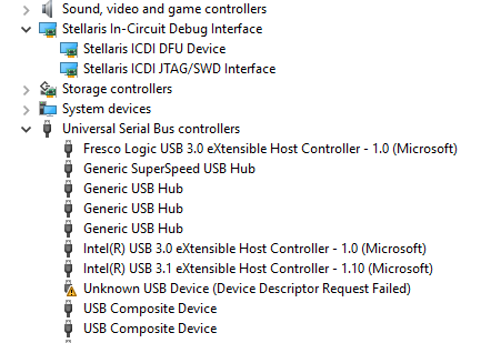
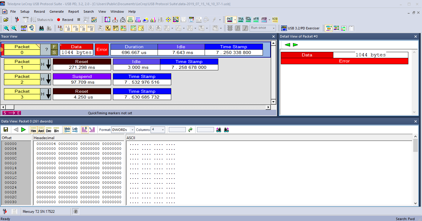
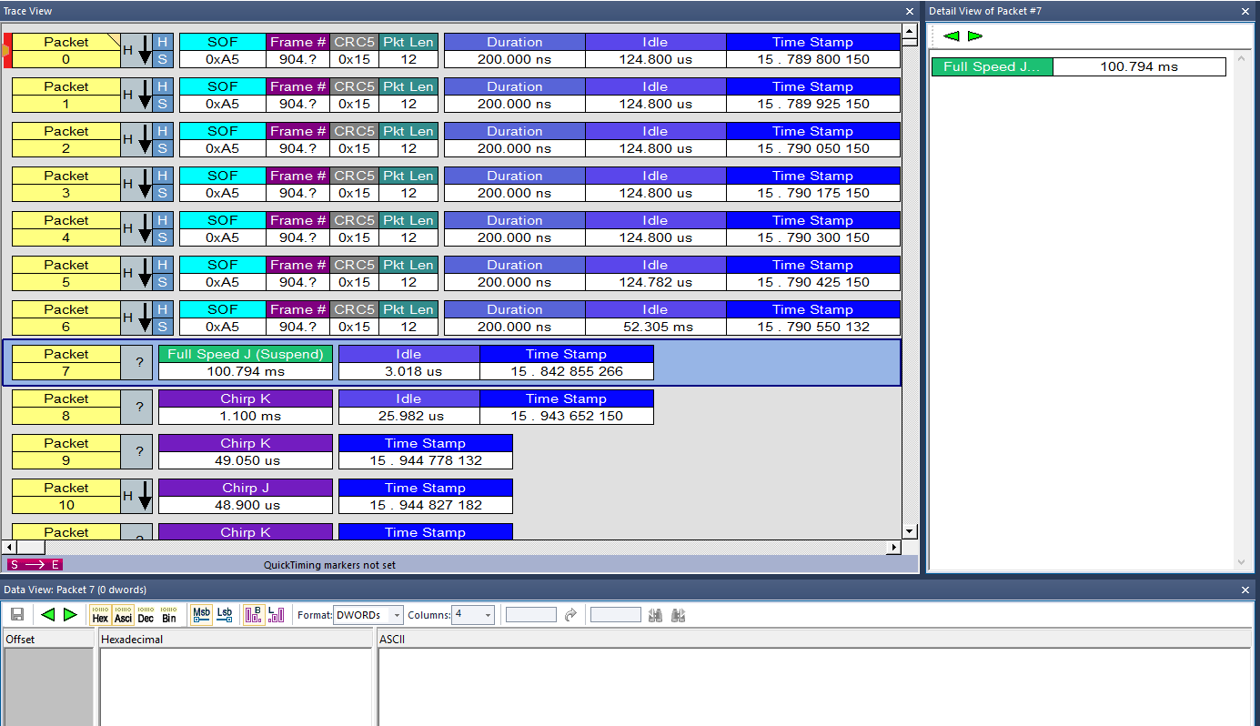
I am using the DK-TM4C129X board as a Bulk Transfer device. Everything works fine when my Windows host is connected to the OTG USB port, but the transfer rate is only 800KB/s, I need it to be 40MB/s. I think the problem is that the OTG port is a USB 1.1 port. I understand this board has a USB2.0 MAC. How can I make this board to connect to host as a USB 2.0 device? What hardware and software changes do I have to make? Is there another Ti development board that supports USB2.0 device?

Thanks

  • Hello Phil,

    The board does not have a USB 2.0 PHY installed, you would need to interface one to it via the EPI ULPI interface.

    We don't have a development board that we sell with USB 2.0 capability, but we do have a TI design including BOM and gerbers for a board had been made and tested to support USB 2.0.

    It also has software which you could use if you decide to try and add a USB PHY to the EPI ULPI interface. This will show you the software changes required.

    The TI Design link is: http://www.ti.com/tool/TIDM-TM4C129USBHS

  • Hi Ralph,

    I am using the example project usb_dev_bulk, and trying to add code to enable the USB high speed support.

    I checked out the project TM4C129USBHS-1.0\tidm_tm4c129cusbhs2ethernet, and copied the High Speed related code to main() function in the usb_dev_bulk.c.

    I noticed that driver/pinout.c file contains a function USBULPIPinoutSet(), so I defined USE_ULPI to include this function.

    In the main(), I added USBULPIPinoutSet() after PinoutSet(). I also added USBDCDFeatureSet(0, USBLIB_FEATURE_USBULPI, &ui32ULPI)  after setting the USBPLL.     

    SysCtlVCOGet(SYSCTL_XTAL_25MHZ, &ui32PLLRate);
    USBDCDFeatureSet(0, USBLIB_FEATURE_CPUCLK, &ui32SysClock);
    USBDCDFeatureSet(0, USBLIB_FEATURE_USBPLL, &ui32PLLRate);

    ui32ULPI = USBLIB_FEATURE_ULPI_HS;                              //set ULPI option for high speed
    USBDCDFeatureSet(0, USBLIB_FEATURE_USBULPI, &ui32ULPI);         //this causes USBDBulkInit() to lockup

    But setting USBLIB_FEATURE_USBULPI causes the function USBDBulkInit(0, &g_sBulkDevice) to lock up.

    What am I missing? BTW, I do not have any USB2.0 PHY installed yet. I am ordering the USB3300 module from Amazon.

    Another question is about controlling the GPIOs to reset and enable the PHY module.

    Which spare GPIO can I use on the DK-TM4C129X? How can I make them as output. I am little confuse on that.

    In the main() of tidm_tm4c129cusbhs2ethernet.c, I see that it use few GPIO to control the reset to PHY. But I don't see those IO pins brought out to the connector. I assume below code cannot be used directly for my board. Again, which spare IO can I use?

    bUSBBusMode = true;
    GPIOPinWrite(GPIO_PORTH_BASE, (GPIO_PIN_2 | GPIO_PIN_3), GPIO_PIN_3);

    //
    // Switch to USBHS and Release Reset to the ULPI PHY
    //
    MAP_GPIOPinWrite(GPIO_PORTD_BASE, GPIO_PIN_7, 0);
    MAP_GPIOPinWrite(GPIO_PORTE_BASE, GPIO_PIN_5, 0);

    Thanks for all your help.

    Phil

  • Hello Phil,

    If you don't have a PHY attached you can't enable ULPI, it won't work without the PHY because it won't see any data where it looks for it. You need the PHY first.

    Also on my original post I said to put the PHY to the EPI interface but I meant the ULPI headers. You can see them on the left side labeled as ULPI/LPC.

    As far as the GPIO, any spare GPIO not used for ULPI or your other peripherals can be used, there are a lot and there's not a specific recommendation you need to follow, so just pick something that you don't think you'd need the multiplexed peripheral for.

    Also I think for the TI design that was also put together to allow the board to do both FS and HS, so that's up to you how important that kind of functionality is.

  • Ralph,

    Okay, I will try again when I get the USB2.0 PHY.

    BTW, I saw on another post suggesting ui32PLLRate be set to 0. Which way is correct for High Speed?

    //
    // Tell the USB library the CPU clock and the PLL frequency. This is a
    // new requirement for TM4C129 devices.
    //
    SysCtlVCOGet(SYSCTL_XTAL_25MHZ, &ui32PLLRate);
    //ui32PLLRate = 0; //for High Speed PHY ???
    USBDCDFeatureSet(0, USBLIB_FEATURE_CPUCLK, &ui32SysClock);
    USBDCDFeatureSet(0, USBLIB_FEATURE_USBPLL, &ui32PLLRate);

    Have a great July 4th.

    Thanks

    Phil

  • Hello Phil,

    I don't know why it would be set to 0, that doesn't make sense. Also that code seems to be commented out.

    In our HS example code, we set ui32PLLRate based on the actual PLL:

    SysCtlVCOGet(SYSCTL_XTAL_25MHZ, &ui32PLLRate);

  • Hi,

    I got the Waveshare USB3300 Phy module and connected to my DK-TM4C129X board via 3" jumpers. I added USB high speed related codes from TI refernece project tidm_tm4c129cusbhs2ethernet to the usb_dev_bulk.c. In the usb_dev_bulk project property, I added Predefined USE_ULPI so USBULPIPinoutSet() can be called.

    When I ran the code, it locked up at USBDBulkInit() when USBDCDFeatureSet(0, USBLIB_FEATURE_USBULPI, &ui32ULPI) is called with USBLIB_FEATURE_ULPI_HS or FS. Windows host reported "USB device not recognized" and Device Manager showed unknown USB Device (Device Descriptor Request Failed).

    Where is the Descriptor for the USB HS? Do I need to make any change to it?

    I checked the clock pin on the USB3300 module. It outputs a 60 Mhz clock. I tied the reset to ground because the Phy is on always.

    I compared the USB3300 circuit between the Waveshare and TI reference design. I see the ID is pull up on TI design, and Waveshare is connected to the USB connector. I probed the ID pin on the Waveshare USB3300 module, and it is high. I think the ID pin is not the issue here.

    I attached my project usb_dev_bulk-HS and schematic for the USB3300 module and TI USBHS design. Please review my code to see I missed any.

    Is there a way that I can ship you a Waveshare USB3300 module, so you can help to get it to work?

    Will TI make another DK board with USB 2.0 Phy?

    Please help.

    Thanks

    Phil

    USB3300-USB-HS-Board-Schematic.pdfSchematic_tidrpl3.pdfusb_dev_bulk-HS.zip

  • Hello Phil,

    All the initialization looks right, and if the bus wasn't communicating properly I don't believe you'd see the descriptor failure. It looks like you are using the same descriptor from the design so that should be good too.

    Have you tried using the latest USB drivers from: http://software-dl.ti.com/tiva-c/SW-TM4C/latest/exports/SW-TM4C-2.1.4.178.PATCH-1.0.zip

    If that doesn't work, you are going to want to get hold of a USB analyzer so you can see the bus traffic to debug. I could help on that front if you can post logs and I can look at what is failing about the descriptor.

    Unfortunately receiving hardware for debug is not something we do for E2E support.

  • Ralph,

    Yes, I am using the latest Win driver from TI.

    I cut the jumpers length to about 1" for connecting the USB3300 module to the DK board. When I power on the board, Windows gets unrecognized device. When I depress reset, nothing happens.

    Attached is the screen shot from the Lecroy Mercury USB Analyzer. please take a look.

    I also tried toggling the reset to USB3300, it did not help. Windows sees no device at all.

    Thanks

    Phil

  • Ralph,

    I depressed board reset until code passed the USBDBulkInit(), and USB analyzer captured traffic. Please see attached screen shot. I want to export the data, but not sure how.

    Windows did not see any USB device from this DK board's ULPI.

    Please help.

    Thanks

    Phil

  • Hi Ralph,

    I got the USB3300 to work. For some reason, USBPLL has to be set to 0. Does anyone know why?

    ui32PLLRate = 0;               //must set to 0 for High Speed PHY
    USBDCDFeatureSet(0, USBLIB_FEATURE_CPUCLK, &ui32SysClock);
    USBDCDFeatureSet(0, USBLIB_FEATURE_USBPLL, &ui32PLLRate);

    Now, Windows sees the DK's ULPI as high speed USB device. However, I could get only 7.8MB/s transfer rate. On my other project that I use Cypress FX3, I can get transfer rate up to 46.5MB/s.

    I had already set the BULK_BUFFER_SIZE to 2048 or 4096, and commented out all data processing and graphic codes. Transfer rate on this ULPI port is still only 7.8MB/s. 

    What has to be done to increase the bulk transfer rate?

    Please help.

    Thanks

    Phil

  • Hello Phil,

    I am not sure what happened with my reply yesterday but it seems it didn't go through, sorry about that. Though my suggestion wouldn't have helped as I was thinking it could be wiring related. I don't have any HS hardware on my end unfortunately.

    With that said, I will have to look into why that is needed for HS...

    Regarding transfer speed, you will need to use the USB DMA to get the throughput higher. That is an example I have on my to-do list to put together but haven't got around to yet. I may be able to find a couple of code hints for you to try out though, let me see what I can fish up tomorrow. I think another thing you could try and do is enable double buffering as well.

    Also did you verify that the data transfer is at 512 bytes per packet?

    Also, while looking up the details of the module, I noticed it wasn't even 10 bucks... so one is on it's way to me. Not sure how long the ship time is, but when it arrives I can try and debug on my end as well if you don't get any breakthroughs.

  • Hi Ralph,

    Glad to hear from you. I am really stuck on the transfer rate although the DK board now can connect to host at high speed mode. Yes, it transfers data packet of 512 bytes. Beside the USBPLL needs to set to 0, I was using jumper wires that are too long for connecting the USB3300. I built two versions, one with a proto board, another with 1" jumpers. Both the proto board and 1" jumpers work fine. (see pictures)

    Also attached the picture for USB Transfer. The first 512 bytes data packet started at 11.433.492 sec, it took about 8.667 usec to complete (60Mhz). However, it took about 64 usec to start transferring next 512 bytes. Therefor, the effective transfer rate is 512/64usec = 8 MB/s.

    Please show me how to use double buffering and USB DMA to increase the transfer rate to 40MB/s.

    Thanks

    Phil

    USB3300

  • Hello Phil,

    How time sensitive is this setup for you? The USB3300 kit hasn't shipped yet, but I'd feel much more comfortable trying to test it out first. I don't have USB DMA code available right now, though I have a pretty good idea on what needs to be done for HS which would include a few USB library tweaks. But without being able to test on my end, it would be difficult for me to try and walk you through everything and I'd prefer to just put the example together myself with HS and DMA working and go from there.

  • Ralph,

    That is great that you are getting the same USB3300 module. Please get it to work on your side first. I can wait.

    Where can I find the development manual fro the TiVA USB library? I did not see any in my installed folder.

    Thanks

    Phil

  • Ralph,

    In this usb_dev_bulk project, I also need to set up the Endpoint 0 (Control) to send and receive short command messages. I looked thru all examples and I could not find any relevant code to set up EP0.

    How do I set up EP0 and receive handler to receive control message from host, and then send back a response message?

    Thanks

    Phil

  • Hello Phil,

    EP0 is setup by the USB library and transmits data based on usblib, which is why you aren't seeing code in the example.

    API's like USBDCDSendDataEP0 and USBDCDRequestDataEP0 are used to control EP0, but I've never tried using them in an application layer. They should work with the HandleEP0DataReceived and HandleEP0DataSent handlers within usbdhid.c. Maybe that will help you down the right path for EP0 packets?

    By the way, how long did it take for you to receive the Waveshare EVM?

  • Hi Ralph,

    I ordered three USB3300 from Amazon, and it took 3 to 4 days. Shipping label shows it was shipped by Contempo Views Inc, 172 Trade St. Lexington KY 40511

    About the EP0 communication, I traced the code before receiving your message, and found that the usbdbulk.c does not implement any handler for the EP0. What I need is to receive the Vendor Request from host in my application. In usbdbulk.c - tCustomHandlers g_sBulkHandlers structure, I added an entry HandleRequest to trap for non-standard request from EP0. It does work. In this HandleRequest routine, I case thru the Request Type, and save the wValue to a global variable. In application. the main loop just looks for the change of the wValue. Pretty sure there is a better way. I am just surprise that TI usblib does not provide an easy way for application to communicate via EP0.

    Hope you will get your USB3300 module soon. I read the document and saw some functions related to USB DMA, just not sure how to set them up.

    Thanks

    Phil

  • Hi Phil,

    I had tried ordering from a 3rd party site that hasn't shipped yet. Ordered another from Prime just now should get on Saturday. Thanks for that tip, Amazon didn't show up on 1st page of Google results so I didnt think to look there.

    I didn't develop the USB library so I can't comment on the reasoning (if any) for not having better EP0 support... but at least you found a way around it. If I think of a more elegant solution, I'll let you know.

  • Hi Phil,

    Curious had you yet modified the EP1 bulk transfer packet size from 64 bytes to 256 or 512? Also if not mistaken the USB 1.1 EP0 descriptor might need to be modified (parameters) to indicate USB2.0 hand shake. Not sure of the sample code has the configuration below though it might assist. 

        /* Configure EP_0/1 (RAM) IN/OUT start address, 0,64,576 bytes into FIFO
         * Must be on 8 byte boundary EP_0 reserves first 16 Bytes for control port data. */
        //MAP_USBFIFOConfigSet(USB0_BASE, USB_EP_0, 0, USB_FIFO_SZ_64, USB_EP_DEV_OUT);
        MAP_USBFIFOConfigSet(USB0_BASE, USB_EP_1, 64, USB_FIFO_SZ_512, USB_EP_DEV_OUT); //USB_EP_HOST_OUT
        MAP_USBFIFOConfigSet(USB0_BASE, USB_EP_1, 576, USB_FIFO_SZ_512, USB_EP_DEV_IN); //USB_EP_HOST_IN
    
        /* Configure IN endpoint DMA channel mode 1 typically used for transfers that
         * span multiple packets and do not require interrupts between packets.
         * Configure IN endpoint DMA channel mode 0 typically used for transfers
         * not spanning multiple packets or when INTS are required for each packet. */
        MAP_USBEndpointDMAConfigSet(USB0_BASE, USB_EP_1,
                                USB_EP_DEV_IN | USB_EP_DMA_MODE_0 | USB_EP_AUTO_SET | USB_EP_AUTO_REQUEST); 
        /* Configure DMA channel mode 1 for OUT endpoint 1 */
        MAP_USBEndpointDMAConfigSet(USB0_BASE, USB_EP_1,
                                USB_EP_DEV_OUT | USB_EP_DMA_MODE_0 | USB_EP_AUTO_CLEAR);//USB_EP_AUTO_REQUEST (EPn Host)
        /* Configure USB0 IN/OUT endpoint 1 for 16-1023 byte data packet size.
         * USB_EP_2,USB_EP_3,USB_EP_4,USB_EP_5,USB_EP_6,USB_EP_7 */
        MAP_USBDevEndpointConfigSet(USB0_BASE, USB_EP_1 , 512,
                                (USB_EP_MODE_BULK|USB_EP_AUTO_SET|USB_EP_AUTO_CLEAR));//USB_EP_AUTO_REQUEST (EPn Host)


  • Ralph,

    I did not modify the USB library for packet size of 512. I believe that it is all handled by the library when we set USBLIB_FEATURE_USBULPI = USBLIB_FEATURE_ULPI_HS

    ui32ULPI = USBLIB_FEATURE_ULPI_HS; //USB-HS, set ULPI option for high speed
    USBDCDFeatureSet(0, USBLIB_FEATURE_USBULPI, &ui32ULPI);

    Both my Linux console and USB analyzer state that the DK board's ULPI port is connected as High Speed, and packet size is 512 bytes.

    In usblib\dev\usbbulk.c, line 1181, it checks for USBLIB_FEATURE_USBULPI == USBLIB_FEATURE_ULPI_HS, and uses the High Speed descriptor g_ppBulkConfigDescriptorsHS.

    About the code you attached, none of them is in the sample code, and I am confuse on what and where to add them to increase the bulk transfer speed. Currently,my DK's ULPI port highest bulk transfer rate is about 7.5 MB/s.

    Have you received your USB3300 board? Please help me to set up the DMA and FIFO to achieve higher transfer rate of about 40 MB/s.

    Thanks again.

    Phil


  • Hello Phil,

    I have. Could you send me what you have done on your project? I can get it from you privately if needed. That'd save me a lot of time to get it running to the point I can add the DMA functionality.

  • Phil Chu said:
    About the code you attached,

    Note It was not Ralph who attached this code. You can add it into (usb_dev.bulk.c) after setting up ULPI modes and after USBDBulkInit() is called. Seem to think USB2.0 EP1-7 can support 1024 packet sizes, check to be sure. Microsoft bulk client may also support 1024 byte packets via lmusbdll.lib.

  • Hello Phil/BP101,

    Regarding USB EP0, the specifications are that for high speed EP0 is set to 64 Bytes. There is not a 512 byte EP0 configuration allowed. For that mode. Only Superspeed mode - which is beyond what TM4C can support - has a specification for 512 bytes on EP0.

  • Ralph Jacobi said:
    Regarding USB EP0, the specifications are that for high speed EP0 is set to 64 Bytes

    Right agree the TI coded MS driver simply ignores larger packet sizes set for EP0. However I was referring to EP1-7 where bulk or other data packet transfer occur may allow interrupt transfers, 1024 byte packet size according USB2.0 knowledge base link. There are other places of generalized info about maximum packet size, digging the web link seems to mix USB1.1 and USB2.0, text fails to clarify which one.   

    https://www.beyondlogic.org/usbnutshell/usb4.shtml#Bulk

  • Ralph/BP101,

    Attached is my usb_dev_bulk_HS project. My objective is to transfer a large file (i.e.78KB to 10MB) from host to the device's memory as fast as possible (40MB/s). In my current code, I send an image (pnm in C binary) file to the device and display the data to LCD just for demonstration purpose. So far the transfer rate is about 7.5MB/s.

    I had tried the code from BP101 and DMA setup code from TivaWare™ Peripheral Driver Library User's Guide, section 32.4.5 - Using the integrated USB DMA Controller - Receiving a Multiple Packets. But I did not see any data get transferred to the user array. Transfer rate is still the same. I also tried with different USB buffer sizes. I set the size to 78000 so it can fit my image data. I skipped all the data processing code.

    I am using the Cypress FX3 Streamer Windows application to check the transfer rate because I don't have anything else. I modified the Vendor and Product ID to Cypress FX3 so device can be recognized by the Streamer application.

    I also used the LeCroy Mecury USB analyzer to measure the transfer rate. It took 70 us from 512 bytes packet to packet. That is 7.3 MB/s.

    Thanks in advance for all your help.

    Phil

    usb_dev_bulk-HS_TI_20190730.zip

  • Hello Phil,

    Thanks a lot for the project, I haven't had a ton of time today to work on it unfortunately so I haven't got it all brought up yet. Will update again tomorrow.

  • Ralph,

    Please note that I connect the USB3300's reset line to DK board PG1. I attached the image binary files of a space shuttle and SpaceX in pnm C array format. If you set the BULK_BUFFER_SIZE = 81920, and change the drawing line to GrImageDraw(&g_sContext, g_pui8USBRxBuffer, 0, 0), you will see the image be displayed on LCD in color when you send the file down to the board. You may want to uncomment the line USBBufferInit(&g_sRxBuffer) so you can send the image again.  Please let me know if you want to try the Cypress FX3 Streamer tool to benchmark the transfer rate.

    I kept trying different DMA setup, I just could not get the DMA to transfer data to memory.

    Thanksimage.zip

  • Hello Phil,

    Yeah I saw the PG1 adjustment, I approve of the convenient pin choice :)

    Unfortunately, I hit a snag on my end as I managed to crash my DK board and am trying to recover it still. Still scratching my head as to how I managed to do that, but in any case, need to get that back up and running to test further...

    I did look into the USB DMA topic in more detail and found the following explanation regarding DMA configuration:

    //*****************************************************************************
    //
    // The control table used by the uDMA controller.  This table must be aligned
    // to a 1024 byte boundary.  In this application uDMA is only used for USB,
    // so only the first 6 channels are needed.
    //
    //*****************************************************************************
    #if defined(__ICCARM__)
    #pragma data_alignment=1024
    tDMAControlTable g_sDMAControlTable[6];
    #elif defined(__TI_ARM__)
    #pragma DATA_ALIGN(g_sDMAControlTable, 1024)
    tDMAControlTable g_sDMAControlTable[6];
    #else
    tDMAControlTable g_sDMAControlTable[6] __attribute__ ((aligned(1024)));
    #endif
    

    And this is the only other code used based on that:

        //
        // Enable the uDMA controller and set up the control table base.
        //
        ROM_SysCtlPeripheralEnable(SYSCTL_PERIPH_UDMA);
        ROM_uDMAEnable();
        ROM_uDMAControlBaseSet(g_sDMAControlTable);

    I will need to test on my end about if that's sufficient for high speed though.

    One other thing that I was thinking about your application is I wonder if the graphic piece is adding a bottleneck of some sort. On my end, I'm planning to test the speed with a simple data loopback test that is designed to stress the transmit capabilities of the device.

    Also there were a couple fixes for the USB library regarding DMA specifically for high speed that are coming in the next TivaWare update, they may be worth you adding, especially since I will be testing with those in.

    I would suggest trying to add these fixes (which requires you to re-build usblib so that they are properly compiled) and reverting the DMA code to the basic setup posted above and then see what happens performance wise. The fixes include using Max Packet Size rather than 64 bytes as part of the DMA transfers in the UsbLib, so it could have a significant throughput improvement.

    The files are attached here:

    usblib/usbdma.c

    1856.usbdma.c
    //*****************************************************************************
    //
    // usbdma.c - USB Library DMA handling functions.
    //
    // Copyright (c) 2012-2017 Texas Instruments Incorporated.  All rights reserved.
    // Software License Agreement
    // 
    // Texas Instruments (TI) is supplying this software for use solely and
    // exclusively on TI's microcontroller products. The software is owned by
    // TI and/or its suppliers, and is protected under applicable copyright
    // laws. You may not combine this software with "viral" open-source
    // software in order to form a larger program.
    // 
    // THIS SOFTWARE IS PROVIDED "AS IS" AND WITH ALL FAULTS.
    // NO WARRANTIES, WHETHER EXPRESS, IMPLIED OR STATUTORY, INCLUDING, BUT
    // NOT LIMITED TO, IMPLIED WARRANTIES OF MERCHANTABILITY AND FITNESS FOR
    // A PARTICULAR PURPOSE APPLY TO THIS SOFTWARE. TI SHALL NOT, UNDER ANY
    // CIRCUMSTANCES, BE LIABLE FOR SPECIAL, INCIDENTAL, OR CONSEQUENTIAL
    // DAMAGES, FOR ANY REASON WHATSOEVER.
    // 
    // This is part of revision 2.1.4.178 of the Tiva USB Library.
    //
    //*****************************************************************************
    
    #include <stdbool.h>
    #include <stdint.h>
    #include "inc/hw_memmap.h"
    #include "inc/hw_types.h"
    #include "inc/hw_ints.h"
    #include "inc/hw_sysctl.h"
    #include "inc/hw_udma.h"
    #include "driverlib/debug.h"
    #include "driverlib/interrupt.h"
    #include "driverlib/rtos_bindings.h"
    #include "driverlib/usb.h"
    #include "driverlib/rom.h"
    #include "driverlib/rom_map.h"
    #include "driverlib/udma.h"
    #include "usblib/usblib.h"
    #include "usblib/usblibpriv.h"
    
    //*****************************************************************************
    //
    //! \addtogroup usblib_dma_api Internal USB DMA functions
    //! @{
    //
    //*****************************************************************************
    
    //*****************************************************************************
    //
    // There are two sets of functions in this file, one is used with uDMA while
    // the other is used with USB controllers with an integrated DMA controller.
    // The functions with the IDMA prefix are for the integrated DMA controller and
    // the functions that are specific to the uDMA controller are prefixed with
    // uDMA.  Any common functions are have just the DMA prefix.
    //
    //*****************************************************************************
    static tUSBDMAInstance g_psUSBDMAInst[1];
    
    //*****************************************************************************
    //
    // Macros used to determine if a uDMA endpoint configuration is used for
    // receive or transmit.
    //
    //*****************************************************************************
    #define UDMAConfigIsRx(ui32Config)                                            \
            ((ui32Config & UDMA_SRC_INC_NONE) == UDMA_SRC_INC_NONE)
    #define UDMAConfigIsTx(ui32Config)                                            \
            ((ui32Config & UDMA_DEST_INC_NONE) == UDMA_DEST_INC_NONE)
    
    //*****************************************************************************
    //
    // USBLibDMAChannelStatus() for USB controllers that use the uDMA for DMA.
    //
    //*****************************************************************************
    static uint32_t
    uDMAUSBChannelStatus(tUSBDMAInstance *psUSBDMAInst, uint32_t ui32Channel)
    {
        uint32_t ui32Status;
    
        //
        // Initialize the current status to no events.
        //
        ui32Status = USBLIBSTATUS_DMA_IDLE;
    
        //
        // Check if there is a pending DMA transfer.
        //
        if(psUSBDMAInst->ui32Complete & (1 << (ui32Channel - 1)))
        {
            //
            // Return that the DMA transfer has completed and clear the
            // DMA pending flag.
            //
            ui32Status = USBLIBSTATUS_DMA_COMPLETE;
        }
        else if(psUSBDMAInst->ui32Pending & (1 << (ui32Channel - 1)))
        {
            //
            // DMA transfer is still pending.
            //
            ui32Status = USBLIBSTATUS_DMA_PENDING;
        }
        else
        {
            //
            // DMA transfer is still pending.
            //
            ui32Status = USBLIBSTATUS_DMA_IDLE;
        }
    
        return(ui32Status);
    }
    
    //*****************************************************************************
    //
    // USBLibDMAChannelStatus() for USB controllers with an integrated DMA
    // controller.
    //
    //*****************************************************************************
    static uint32_t
    iDMAUSBChannelStatus(tUSBDMAInstance *psUSBDMAInst, uint32_t ui32Channel)
    {
        uint32_t ui32Status;
    
        //
        // Initialize the current status to no events.
        //
        ui32Status = USBLIBSTATUS_DMA_IDLE;
    
        //
        // Check if an error has occurred.
        //
        if(USBDMAChannelStatus(psUSBDMAInst->ui32Base, ui32Channel) ==
           USB_DMA_STATUS_ERROR)
        {
            ui32Status = USBLIBSTATUS_DMA_ERROR;
        }
        //
        // Otherwise check if there a pending DMA transfer has completed.
        //
        else if(psUSBDMAInst->ui32Complete & (1 << (ui32Channel - 1)))
        {
            //
            // Return that the DMA transfer has completed and clear the
            // DMA pending flag.
            //
            ui32Status = USBLIBSTATUS_DMA_COMPLETE;
        }
        else if(psUSBDMAInst->ui32Pending & (1 << (ui32Channel - 1)))
        {
            //
            // DMA transfer is still pending.
            //
            ui32Status = USBLIBSTATUS_DMA_PENDING;
        }
        else
        {
            //
            // DMA Channel is idle.
            //
            ui32Status = USBLIBSTATUS_DMA_IDLE;
        }
    
        return(ui32Status);
    }
    
    //*****************************************************************************
    //
    // USBLibDMAIntStatus() for USB controllers that use uDMA.
    //
    //*****************************************************************************
    static uint32_t
    uDMAUSBIntStatus(tUSBDMAInstance *psUSBDMAInst)
    {
        uint32_t ui32Status, ui32Pending;
        int32_t i32Channel;
    
        //
        // Initialize the current status to no events.
        //
        ui32Status = 0;
    
        //
        // No pending interrupts by default.
        //
        ui32Status = 0;
    
        //
        // Save the pending channels.
        //
        ui32Pending = psUSBDMAInst->ui32Pending;
    
        //
        // Loop through channels to find out if any pending DMA transfers have
        // completed.
        //
        for(i32Channel = 0; i32Channel < USB_MAX_DMA_CHANNELS; i32Channel++)
        {
            //
            // If pending and stopped then the DMA completed.
            //
            if((ui32Pending & 1) &&
               (MAP_uDMAChannelModeGet(i32Channel) == UDMA_MODE_STOP))
            {
                ui32Status |= (1 << i32Channel);
            }
            ui32Pending >>= 1;
    
            //
            // Done if this is zero.
            //
            if(ui32Pending == 0)
            {
                break;
            }
        }
    
        return(ui32Status);
    }
    
    //*****************************************************************************
    //
    // USBLibDMAIntStatus() for USB controllers with an integrated DMA controller.
    //
    //*****************************************************************************
    static uint32_t
    iDMAUSBIntStatus(tUSBDMAInstance *psUSBDMAInst)
    {
        //
        // Read the current DMA status, unfortunately this clears the
        // pending interrupt status.
        //
        return(USBDMAChannelIntStatus(psUSBDMAInst->ui32Base));
    }
    
    //*****************************************************************************
    //
    // USBLibDMAIntStatusClear() for USB controllers that use uDMA for DMA or have
    // an integrated DMA controller.
    //
    //*****************************************************************************
    static void
    DMAUSBIntStatusClear(tUSBDMAInstance *psUSBDMAInst, uint32_t ui32Status)
    {
        //
        // Clear out the requested interrupts.  Since the USB interface does not
        // have a true interrupt clear, this clears the current completed
        // status for the requested channels.
        //
        psUSBDMAInst->ui32Complete &= ~ui32Status;
    
        return;
    }
    
    //*****************************************************************************
    //
    // USBLibDMAIntHandler() for USB controllers that use uDMA for DMA or have an
    // integrated DMA controller.
    //
    //*****************************************************************************
    static void
    DMAUSBIntHandler(tUSBDMAInstance *psUSBDMAInst, uint32_t ui32DMAIntStatus)
    {
        uint32_t ui32Channel;
    
        if(ui32DMAIntStatus == 0)
        {
            return;
        }
    
        //
        // Determine if the uDMA is used or the USB DMA controller.
        //
        for(ui32Channel = 0; ui32Channel < USB_MAX_DMA_CHANNELS; ui32Channel++)
        {
            //
            // Mark any pending interrupts as completed.
            //
            if(ui32DMAIntStatus & 1)
            {
                psUSBDMAInst->ui32Pending &= ~(1 << ui32Channel);
                psUSBDMAInst->ui32Complete |= (1 << ui32Channel);
            }
    
            //
            // Check the next channel.
            //
            ui32DMAIntStatus >>= 1;
    
            //
            // Break if there are no more pending DMA interrupts.
            //
            if(ui32DMAIntStatus == 0)
            {
                break;
            }
        }
    }
    
    //*****************************************************************************
    //
    // USBLibDMAChannelEnable() for USB controllers that use uDMA.
    //
    //*****************************************************************************
    static void
    uDMAUSBChannelEnable(tUSBDMAInstance *psUSBDMAInst, uint32_t ui32Channel)
    {
        uint32_t ui32IntEnabled;
    
        //
        // Save if the interrupt was enabled or not.
        //
        ui32IntEnabled = IntIsEnabled(psUSBDMAInst->ui32IntNum);
    
        //
        // Disable the USB interrupt if it was enabled.
        //
        if(ui32IntEnabled)
        {
            OS_INT_DISABLE(psUSBDMAInst->ui32IntNum);
        }
    
        //
        // Mark this channel as pending and not complete.
        //
        psUSBDMAInst->ui32Pending |= (1 << (ui32Channel - 1));
        psUSBDMAInst->ui32Complete &= ~(1 << (ui32Channel - 1));
    
        //
        // Enable DMA for the endpoint.
        //
        if(UDMAConfigIsRx(psUSBDMAInst->pui32Config[ui32Channel - 1]))
        {
            MAP_USBEndpointDMAEnable(psUSBDMAInst->ui32Base,
                                     psUSBDMAInst->pui8Endpoint[ui32Channel - 1],
                                     USB_EP_DEV_OUT | USB_EP_HOST_IN);
        }
        else
        {
            MAP_USBEndpointDMAEnable(psUSBDMAInst->ui32Base,
                                     psUSBDMAInst->pui8Endpoint[ui32Channel - 1],
                                     USB_EP_DEV_IN | USB_EP_HOST_OUT);
        }
    
        //
        // Enable the DMA in the uDMA controller.
        //
        MAP_uDMAChannelEnable(ui32Channel - 1);
    
        //
        // Enable the USB interrupt if it was enabled before.
        //
        if(ui32IntEnabled)
        {
            OS_INT_ENABLE(psUSBDMAInst->ui32IntNum);
        }
    }
    
    //*****************************************************************************
    //
    // USBLibDMAChannelEnable() for USB controllers with an integrated DMA
    // controller.
    //
    //*****************************************************************************
    static void
    iDMAUSBChannelEnable(tUSBDMAInstance *psUSBDMAInst, uint32_t ui32Channel)
    {
        uint32_t ui32IntEnabled;
    
        //
        // Save if the interrupt was enabled or not.
        //
        ui32IntEnabled = IntIsEnabled(psUSBDMAInst->ui32IntNum);
    
        //
        // Disable the USB interrupt if it was enabled.
        //
        if(ui32IntEnabled)
        {
            OS_INT_DISABLE(psUSBDMAInst->ui32IntNum);
        }
    
        //
        // Mark this channel as pending and not complete.
        //
        psUSBDMAInst->ui32Pending |= (1 << (ui32Channel - 1));
        psUSBDMAInst->ui32Complete &= ~(1 << (ui32Channel - 1));
    
        //
        // Enable the interrupt for this DMA channel.
        //
        USBDMAChannelIntEnable(psUSBDMAInst->ui32Base, ui32Channel - 1);
    
        //
        // Enable the DMA channel.
        //
        USBDMAChannelEnable(psUSBDMAInst->ui32Base, ui32Channel - 1);
    
        //
        // Enable the USB interrupt if it was enabled before.
        //
        if(ui32IntEnabled)
        {
            OS_INT_ENABLE(psUSBDMAInst->ui32IntNum);
        }
    }
    
    //*****************************************************************************
    //
    // USBLibDMAChannelDisable() for USB controllers that use uDMA.
    //
    //*****************************************************************************
    static void
    uDMAUSBChannelDisable(tUSBDMAInstance *psUSBDMAInst, uint32_t ui32Channel)
    {
        //
        // Disable DMA for the endpoint.
        //
        if(UDMAConfigIsRx(psUSBDMAInst->pui32Config[ui32Channel - 1]))
        {
            MAP_USBEndpointDMADisable(psUSBDMAInst->ui32Base,
                                      psUSBDMAInst->pui8Endpoint[ui32Channel - 1],
                                      USB_EP_DEV_OUT);
        }
        else
        {
            MAP_USBEndpointDMADisable(psUSBDMAInst->ui32Base,
                                      psUSBDMAInst->pui8Endpoint[ui32Channel - 1],
                                      USB_EP_DEV_IN);
        }
    
        //
        // Disable the DMA channel in the uDMA controller.
        //
        MAP_uDMAChannelDisable(ui32Channel - 1);
    
        //
        // Clear out any pending or complete flag set for this DMA channel.
        //
        psUSBDMAInst->ui32Pending &= ~(1 << (ui32Channel - 1));
        psUSBDMAInst->ui32Complete &= ~(1 << (ui32Channel - 1));
    }
    
    //*****************************************************************************
    //
    // USBLibDMAChannelDisable() for USB controllers with an integrated DMA
    // controller.
    //
    //*****************************************************************************
    static void
    iDMAUSBChannelDisable(tUSBDMAInstance *psUSBDMAInst, uint32_t ui32Channel)
    {
        //
        // Disable the DMA channel.
        //
        USBDMAChannelDisable(psUSBDMAInst->ui32Base, ui32Channel - 1);
    
        //
        // Disable the interrupt for this DMA channel.
        //
        USBDMAChannelIntDisable(psUSBDMAInst->ui32Base, ui32Channel - 1);
    
        //
        // Clear out any pending or complete flag set for this DMA channel.
        //
        psUSBDMAInst->ui32Pending &= ~(1 << (ui32Channel - 1));
        psUSBDMAInst->ui32Complete &= ~(1 << (ui32Channel - 1));
    }
    
    //*****************************************************************************
    //
    // USBLibDMAChannelIntEnable() for USB controllers that use uDMA.
    //
    //*****************************************************************************
    static void
    uDMAUSBChannelIntEnable(tUSBDMAInstance *psUSBDMAInst, uint32_t ui32Channel)
    {
        //
        // There is no way to Enable channel interrupts when using uDMA.
        //
    }
    
    //*****************************************************************************
    //
    // USBLibDMAChannelIntEnable() for USB controllers with an integrated DMA
    // controller.
    //
    //*****************************************************************************
    static void
    iDMAUSBChannelIntEnable(tUSBDMAInstance *psUSBDMAInst, uint32_t ui32Channel)
    {
        //
        // Enable the interrupt for this DMA channel.
        //
        USBDMAChannelIntEnable(psUSBDMAInst->ui32Base, ui32Channel - 1);
    }
    
    //*****************************************************************************
    //
    // USBLibDMAChannelIntDisable() for USB controllers that use uDMA.
    //
    //*****************************************************************************
    static void
    uDMAUSBChannelIntDisable(tUSBDMAInstance *psUSBDMAInst, uint32_t ui32Channel)
    {
        //
        // There is no way to Disable channel interrupts when using uDMA.
        //
    }
    
    //*****************************************************************************
    //
    // USBLibDMAChannelIntDisable() for USB controllers with an integrated DMA
    // controller.
    //
    //*****************************************************************************
    static void
    iDMAUSBChannelIntDisable(tUSBDMAInstance *psUSBDMAInst, uint32_t ui32Channel)
    {
        //
        // Disable the interrupt for this DMA channel.
        //
        USBDMAChannelIntDisable(psUSBDMAInst->ui32Base, ui32Channel - 1);
    }
    
    //*****************************************************************************
    //
    // USBLibDMATransfer() for USB controllers that use the uDMA controller.
    //
    //*****************************************************************************
    static uint32_t
    uDMAUSBTransfer(tUSBDMAInstance *psUSBDMAInst, uint32_t ui32Channel,
                    void *pvBuffer, uint32_t ui32Size)
    {
        void *pvFIFO;
        uint32_t uluDMAChannel;
        uint32_t ui32PacketCount;
        uint32_t ui32TransferCount;
    
        if((ui32Size < 64) || ((uint32_t)pvBuffer & 0x3))
        {
            return(0);
        }
    
        //
        // Mark this channel as pending and not complete.
        //
        psUSBDMAInst->ui32Pending |= (1 << (ui32Channel - 1));
        psUSBDMAInst->ui32Complete &= ~(1 << (ui32Channel - 1));
    
        //
        // Save the pointer to the data and the byte count.
        //
        psUSBDMAInst->ppui32Data[ui32Channel - 1] = pvBuffer;
        psUSBDMAInst->pui32Count[ui32Channel - 1] = ui32Size;
    
        //
        // Need the address of the FIFO.
        //
        pvFIFO = (void *)USBFIFOAddrGet(psUSBDMAInst->ui32Base,
                                    psUSBDMAInst->pui8Endpoint[ui32Channel - 1]);
    
        //
        // Calculate the uDMA channel for this RX channel.
        //
        uluDMAChannel = UDMA_CHANNEL_USBEP1RX + ui32Channel - 1;
    
        ui32TransferCount = ui32Size;
    
        if((psUSBDMAInst->pui32Config[ui32Channel - 1] & UDMA_SIZE_32) ==
           UDMA_SIZE_32)
        {
            ui32TransferCount >>= 2;
        }
        else if((psUSBDMAInst->pui32Config[ui32Channel - 1] & UDMA_SIZE_32) ==
                UDMA_SIZE_32)
        {
            ui32TransferCount >>= 1;
        }
    
        //
        // If source increment is none this is an RX transfer.
        //
        if(UDMAConfigIsRx(psUSBDMAInst->pui32Config[ui32Channel - 1]))
        {
            MAP_uDMAChannelTransferSet(uluDMAChannel, UDMA_MODE_BASIC, pvFIFO,
                                       pvBuffer, ui32TransferCount);
        }
        else
        {
            MAP_uDMAChannelTransferSet(uluDMAChannel, UDMA_MODE_BASIC, pvBuffer,
                                       pvFIFO, ui32TransferCount);
        }
    
        //
        // Set the mode based on the size of the transfer.  More than one
        // packet requires mode 1.
        //
        if(ui32Size > psUSBDMAInst->pui32MaxPacketSize[ui32Channel - 1])
        {
            //
            // Calculate the number of packets required for this transfer.
            //
            ui32PacketCount = ((ui32Size /
                               psUSBDMAInst->pui32MaxPacketSize[ui32Channel - 1]));
    
            //
            // Set the packet count so that the last packet does not generate
            // another IN request.
            //
            USBEndpointPacketCountSet(psUSBDMAInst->ui32Base,
                                      psUSBDMAInst->pui8Endpoint[ui32Channel - 1],
                                      ui32PacketCount);
    
            //
            // Configure the USB endpoint in mode 1 for this DMA transfer.
            //
            USBEndpointDMAConfigSet(psUSBDMAInst->ui32Base,
                                    psUSBDMAInst->pui8Endpoint[ui32Channel - 1],
                                    psUSBDMAInst->pui32EPDMAMode1[ui32Channel - 1]);
        }
        else
        {
            //
            // Configure the USB endpoint in mode 0 for this DMA transfer.
            //
            USBEndpointDMAConfigSet(psUSBDMAInst->ui32Base,
                                    psUSBDMAInst->pui8Endpoint[ui32Channel - 1],
                                    psUSBDMAInst->pui32EPDMAMode0[ui32Channel -1]);
        }
    
        //
        // Enable the uDMA channel to start the transfer
        //
        uDMAUSBChannelEnable(psUSBDMAInst, ui32Channel);
    
        return(ui32Size);
    }
    
    //*****************************************************************************
    //
    // USBLibDMATransfer() for USB controllers with an integrated DMA controller.
    //
    //*****************************************************************************
    static uint32_t
    iDMAUSBTransfer(tUSBDMAInstance *psUSBDMAInst, uint32_t ui32Channel,
                    void *pvBuffer, uint32_t ui32Size)
    {
        uint32_t ui32PacketCount;
    
        if((uint32_t)pvBuffer & 0x3)
        {
            return(0);
        }
    
        //
        // Mark this channel as pending and not complete.
        //
        psUSBDMAInst->ui32Pending |= (1 << (ui32Channel - 1));
        psUSBDMAInst->ui32Complete &= ~(1 << (ui32Channel - 1));
    
        //
        // Save the pointer to the data and the byte count.
        //
        psUSBDMAInst->ppui32Data[ui32Channel - 1] = pvBuffer;
        psUSBDMAInst->pui32Count[ui32Channel - 1] = ui32Size;
    
        //
        // Set the address.
        //
        USBDMAChannelAddressSet(psUSBDMAInst->ui32Base, ui32Channel - 1, pvBuffer);
    
        //
        // Set the number of transfers.
        //
        USBDMAChannelCountSet(psUSBDMAInst->ui32Base, ui32Channel - 1, ui32Size);
    
        //
        // Set the mode based on the size of the transfer.  More than one
        // packet requires mode 1.
        //
        if(ui32Size >= psUSBDMAInst->pui32MaxPacketSize[ui32Channel - 1])
        {
            //
            // Calculate the number of packets required for this transfer.
            //
            ui32PacketCount = ui32Size /
                              psUSBDMAInst->pui32MaxPacketSize[ui32Channel - 1];
    
            if(ui32Size % psUSBDMAInst->pui32MaxPacketSize[ui32Channel - 1])
            {
                ui32PacketCount += 1;
            }
    
            USBEndpointPacketCountSet(psUSBDMAInst->ui32Base,
                                      psUSBDMAInst->pui8Endpoint[ui32Channel - 1],
                                      ui32PacketCount);
    
            //
            // Configure the USB DMA controller for mode 1.
            //
            USBEndpointDMAConfigSet(psUSBDMAInst->ui32Base,
                                    psUSBDMAInst->pui8Endpoint[ui32Channel - 1],
                                    psUSBDMAInst->pui32EPDMAMode1[ui32Channel - 1]);
    
            USBDMAChannelConfigSet(psUSBDMAInst->ui32Base, ui32Channel - 1,
                                   psUSBDMAInst->pui8Endpoint[ui32Channel - 1],
                                   psUSBDMAInst->pui32Config[ui32Channel - 1] |
                                   USB_DMA_CFG_MODE_1);
    
            //
            // Enable DMA on the endpoint.
            //
            if(psUSBDMAInst->pui32Config[ui32Channel - 1] & USB_DMA_CFG_DIR_TX)
            {
                //
                // Make sure that DMA is enabled on the endpoint.
                //
                MAP_USBEndpointDMAEnable(
                                    psUSBDMAInst->ui32Base,
                                    psUSBDMAInst->pui8Endpoint[ui32Channel - 1],
                                    USB_EP_HOST_OUT);
            }
            else
            {
                //
                // Make sure that DMA is enabled on the endpoint.
                //
                MAP_USBEndpointDMAEnable(
                                       psUSBDMAInst->ui32Base,
                                       psUSBDMAInst->pui8Endpoint[ui32Channel - 1],
                                       USB_EP_HOST_IN);
            }
    
            //
            // Enable the DMA channel.
            //
            USBDMAChannelEnable(psUSBDMAInst->ui32Base, ui32Channel - 1);
        }
        else
        {
            //
            // Configure the USB DMA controller for mode 0.
            //
            USBEndpointDMAConfigSet(psUSBDMAInst->ui32Base,
                                    psUSBDMAInst->pui8Endpoint[ui32Channel - 1],
                                    psUSBDMAInst->pui32EPDMAMode0[ui32Channel -1]);
    
            USBDMAChannelConfigSet(psUSBDMAInst->ui32Base, ui32Channel -1,
                                   psUSBDMAInst->pui8Endpoint[ui32Channel - 1],
                                   psUSBDMAInst->pui32Config[ui32Channel - 1] |
                                   USB_DMA_CFG_MODE_0);
    
            //
            // In mode 0 only enable DMA transfer for mode 0.
            //
            if(psUSBDMAInst->pui32Config[ui32Channel - 1] & USB_DMA_CFG_DIR_TX)
            {
                //
                // Make sure that DMA is enabled on the endpoint.
                //
                MAP_USBEndpointDMAEnable(
                                    psUSBDMAInst->ui32Base,
                                    psUSBDMAInst->pui8Endpoint[ui32Channel - 1],
                                    USB_EP_HOST_OUT);
                //
                // Enable the DMA channel.
                //
                USBDMAChannelEnable(psUSBDMAInst->ui32Base, ui32Channel - 1);
            }
            else
            {
                //
                // Make sure that DMA is disabled on the endpoint, it will
                // be enabled when the endpoint interrupt occurs.
                //
                MAP_USBEndpointDMADisable(
                                       psUSBDMAInst->ui32Base,
                                       psUSBDMAInst->pui8Endpoint[ui32Channel - 1],
                                       USB_EP_HOST_IN);
    
                //
                // Returns 0 so that when DMA is not used, the bUseDMA flag in the calling function
                // is set to false.
                //
                return(0);
    
            }
        }
    
        return(ui32Size);
    }
    
    //*****************************************************************************
    //
    // USBLibDMAChannelAllocate() for USB controllers that use uDMA for DMA.
    //
    //*****************************************************************************
    static uint32_t
    uDMAUSBChannelAllocate(tUSBDMAInstance *psUSBDMAInst, uint8_t ui8Endpoint,
                           uint32_t ui32MaxPacketSize, uint32_t ui32Config)
    {
        uint32_t ui32Channel;
    
        //
        // The DMA channels are organized in pairs on this controller and the
        // transmit channels are 1, 3, and 5 while receive are 0, 2, and 4.
        //
        if(ui32Config & USB_DMA_EP_RX)
        {
            ui32Channel = 0;
        }
        else
        {
            ui32Channel = 1;
        }
    
        //
        // Search for an available DMA channel to use.
        //
        for(; ui32Channel < USB_MAX_DMA_CHANNELS_0; ui32Channel += 2)
        {
            //
            // If the current endpoint value is zero then this channel is
            // available.
            //
            if(psUSBDMAInst->pui8Endpoint[ui32Channel] == 0)
            {
                //
                // Save the endpoint for this DMA channel.
                //
                psUSBDMAInst->pui8Endpoint[ui32Channel] = ui8Endpoint;
    
                //
                // Save the maximum packet size for the endpoint.
                //
                psUSBDMAInst->pui32MaxPacketSize[ui32Channel] = ui32MaxPacketSize;
    
                //
                // Set the channel configuration based on the direction.
                //
                if(ui32Config & USB_DMA_EP_RX)
                {
                    psUSBDMAInst->pui32Config[ui32Channel] =
                            UDMA_SIZE_8 | UDMA_SRC_INC_NONE | UDMA_DST_INC_8 |
                            UDMA_ARB_64;
    
                    //
                    // If in device mode and Isochronous.
                    //
                    if(((ui32Config & USB_DMA_EP_HOST) == 0) &&
                       ((ui32Config & USB_DMA_EP_TYPE_M) == USB_DMA_EP_TYPE_ISOC))
                    {
                        //
                        // USB_EP_AUTO_REQUEST is required for device
                        // Isochronous endpoints.
                        //
                        psUSBDMAInst->pui32EPDMAMode0[ui32Channel] =
                                                        USB_EP_DMA_MODE_0 |
                                                        USB_EP_AUTO_REQUEST |
                                                        USB_EP_HOST_IN;
                    }
                    else
                    {
                        psUSBDMAInst->pui32EPDMAMode0[ui32Channel] =
                                                        USB_EP_DMA_MODE_0 |
                                                        USB_EP_AUTO_CLEAR |
                                                        USB_EP_HOST_IN;
                    }
    
                    //
                    // Do not set auto request in device mode unless it is an
                    // isochronous endpoint.
                    //
                    if(((ui32Config & USB_DMA_EP_HOST) == 0) &&
                       ((ui32Config & USB_DMA_EP_TYPE_M) != USB_DMA_EP_TYPE_ISOC))
                    {
                        psUSBDMAInst->pui32EPDMAMode1[ui32Channel] =
                                                    USB_EP_DMA_MODE_1 |
                                                    USB_EP_HOST_IN |
                                                    USB_EP_AUTO_CLEAR;
                    }
                    else
                    {
                        psUSBDMAInst->pui32EPDMAMode1[ui32Channel] =
                                                    USB_EP_DMA_MODE_1 |
                                                    USB_EP_HOST_IN |
                                                    USB_EP_AUTO_REQUEST |
                                                    USB_EP_AUTO_CLEAR;
                    }
                }
                else
                {
                    psUSBDMAInst->pui32Config[ui32Channel] =
                            UDMA_SIZE_8 | UDMA_SRC_INC_8 | UDMA_DST_INC_NONE |
                            UDMA_ARB_64;
    
                    psUSBDMAInst->pui32EPDMAMode0[ui32Channel] = USB_EP_DMA_MODE_0 |
                                                                 USB_EP_HOST_OUT;
                    psUSBDMAInst->pui32EPDMAMode1[ui32Channel] = USB_EP_DMA_MODE_1 |
                                                                 USB_EP_HOST_OUT |
                                                                 USB_EP_AUTO_SET;
                }
    
                //
                // Map the uDMA channel to the given endpoint.
                //
                MAP_USBEndpointDMAChannel(psUSBDMAInst->ui32Base, ui8Endpoint,
                                          ui32Channel);
    
                //
                // Clear out the attributes on this channel.
                //
                MAP_uDMAChannelAttributeDisable(ui32Channel, UDMA_ATTR_ALL);
    
                //
                // Configure the uDMA channel for the pipe
                //
                MAP_uDMAChannelControlSet(ui32Channel,
                                          psUSBDMAInst->pui32Config[ui32Channel]);
    
                if(ui32Config & USB_DMA_EP_RX)
                {
                    MAP_USBEndpointDMADisable(psUSBDMAInst->ui32Base, ui8Endpoint,
                                              USB_EP_DEV_OUT);
                }
                else
                {
                    MAP_USBEndpointDMADisable(psUSBDMAInst->ui32Base, ui8Endpoint,
                                              USB_EP_DEV_IN);
                }
    
                //
                // Outside of this function all channels are 1 based as
                // zero is not a valid channel.
                //
                return(ui32Channel + 1);
            }
        }
        return(0);
    }
    
    //*****************************************************************************
    //
    // USBLibDMAChannelAllocate() for USB controllers with an integrated DMA
    // controller.
    //
    //*****************************************************************************
    static uint32_t
    iDMAUSBChannelAllocate(tUSBDMAInstance *psUSBDMAInst, uint8_t ui8Endpoint,
                           uint32_t ui32MaxPacketSize, uint32_t ui32Config)
    {
        uint32_t ui32Channel;
    
        //
        // Search for an available DMA channel to use.
        //
        for(ui32Channel = 0; ui32Channel < USB_MAX_DMA_CHANNELS_0; ui32Channel++)
        {
            //
            // If the current endpoint value is zero then this channel is
            // available.
            //
            if(psUSBDMAInst->pui8Endpoint[ui32Channel] == 0)
            {
                //
                // Clear out the attributes on this channel.
                //
                USBDMAChannelDisable(psUSBDMAInst->ui32Base, ui32Channel);
    
                //
                // Save the endpoint for this DMA channel.
                //
                psUSBDMAInst->pui8Endpoint[ui32Channel] = ui8Endpoint;
    
                //
                // Save the maximum packet size for the endpoint.
                //
                psUSBDMAInst->pui32MaxPacketSize[ui32Channel] = ui32MaxPacketSize;
    
                //
                // Assign the endpoint to the channel and set the direction.
                //
                if(ui32Config & USB_DMA_EP_RX)
                {
                    psUSBDMAInst->pui32Config[ui32Channel] =
                                            USB_DMA_CFG_DIR_RX |
                                            USB_DMA_CFG_BURST_NONE |
                                            USB_DMA_CFG_INT_EN;
    
                    //
                    // If in device mode and Isochronous.
                    //
                    if(((ui32Config & USB_DMA_EP_HOST) == 0) &&
                       ((ui32Config & USB_DMA_EP_TYPE_M) == USB_DMA_EP_TYPE_ISOC))
                    {
                        //
                        // USB_EP_AUTO_REQUEST is required for device
                        // Isochronous endpoints.
                        //
                        psUSBDMAInst->pui32EPDMAMode0[ui32Channel] =
                                                        USB_EP_DMA_MODE_0 |
                                                        USB_EP_AUTO_REQUEST |
                                                        USB_EP_HOST_IN;
                    }
                    else
                    {
                        psUSBDMAInst->pui32EPDMAMode0[ui32Channel] =
                                                        USB_EP_DMA_MODE_0 |
                                                        USB_EP_AUTO_CLEAR |
                                                        USB_EP_HOST_IN;
                    }
    
                    //
                    // Do not set auto request in device mode unless it is an
                    // isochronous endpoint.
                    //
                    if(((ui32Config & USB_DMA_EP_HOST) == 0) &&
                       ((ui32Config & USB_DMA_EP_TYPE_M) != USB_DMA_EP_TYPE_ISOC))
                    {
                        psUSBDMAInst->pui32EPDMAMode1[ui32Channel] =
                                                    USB_EP_DMA_MODE_1 |
                                                    USB_EP_HOST_IN |
                                                    USB_EP_AUTO_CLEAR;
                    }
                    else
                    {
                        psUSBDMAInst->pui32EPDMAMode1[ui32Channel] =
                                                    USB_EP_DMA_MODE_1 |
                                                    USB_EP_HOST_IN |
                                                    USB_EP_AUTO_REQUEST |
                                                    USB_EP_AUTO_CLEAR;
                    }
                }
                else
                {
                    psUSBDMAInst->pui32Config[ui32Channel] =
                                                    USB_DMA_CFG_DIR_TX |
                                                    USB_DMA_CFG_BURST_NONE |
                                                    USB_DMA_CFG_INT_EN;
    
                    psUSBDMAInst->pui32EPDMAMode0[ui32Channel] =
                                                    USB_EP_DMA_MODE_0 |
                                                    USB_EP_HOST_OUT;
                    psUSBDMAInst->pui32EPDMAMode1[ui32Channel] =
                                                    USB_EP_DMA_MODE_1 |
                                                    USB_EP_HOST_OUT |
                                                    USB_EP_AUTO_SET;
                }
    
                //
                // Outside of this function all channels are 1 based as
                // zero is not a valid channel.
                //
                return(ui32Channel + 1);
            }
        }
        return(0);
    }
    
    //*****************************************************************************
    //
    // USBLibDMAChannelRelease() for USB controllers that use uDMA for DMA.
    //
    //*****************************************************************************
    static void
    uDMAUSBChannelRelease(tUSBDMAInstance *psUSBDMAInst, uint8_t ui32Channel)
    {
        ASSERT(ui32Channel < USB_MAX_DMA_CHANNELS_0);
    
        //
        // Clear out the attributes on this channel.
        //
        MAP_uDMAChannelAttributeDisable(ui32Channel - 1, UDMA_ATTR_ALL);
    
        if(psUSBDMAInst->pui8Endpoint[ui32Channel] & USB_DMA_EP_RX)
        {
            MAP_USBEndpointDMADisable(psUSBDMAInst->ui32Base,
                    (psUSBDMAInst->pui8Endpoint[ui32Channel] & ~USB_DMA_EP_RX),
                    USB_EP_DEV_OUT);
        }
        else
        {
            MAP_USBEndpointDMADisable(psUSBDMAInst->ui32Base,
                    (psUSBDMAInst->pui8Endpoint[ui32Channel] & ~USB_DMA_EP_RX),
                    USB_EP_DEV_IN);
        }
    
        //
        // Clear out the state for this endpoint.
        //
        psUSBDMAInst->pui8Endpoint[ui32Channel - 1] = 0;
        psUSBDMAInst->pui32Config[ui32Channel - 1] = 0;
        psUSBDMAInst->ui32Pending &= ~(1 << (ui32Channel - 1));
        psUSBDMAInst->ui32Complete &= ~(1 << (ui32Channel - 1));
        psUSBDMAInst->pui32MaxPacketSize[ui32Channel - 1] = 0;
    }
    
    //*****************************************************************************
    //
    // DMAChannelRelease() for USB controllers with an integrated DMA controller.
    //
    //*****************************************************************************
    static void
    iDMAUSBChannelRelease(tUSBDMAInstance *psUSBDMAInst, uint8_t ui32Channel)
    {
        ASSERT(ui32Channel < USB_MAX_DMA_CHANNELS);
    
        //
        // Clear out the attributes on this channel.
        //
        USBDMAChannelDisable(psUSBDMAInst->ui32Base, ui32Channel);
    
        //
        // Clear out the state for this endpoint.
        //
        psUSBDMAInst->pui8Endpoint[ui32Channel - 1] = 0;
        psUSBDMAInst->pui32Config[ui32Channel - 1] = 0;
        psUSBDMAInst->ui32Pending &= ~(1 << (ui32Channel - 1));
        psUSBDMAInst->ui32Complete &= ~(1 << (ui32Channel - 1));
        psUSBDMAInst->pui32MaxPacketSize[ui32Channel - 1] = 0;
    }
    
    //*****************************************************************************
    //
    // USBLibDMAUnitSizeSet() for USB controllers that use uDMA for DMA.
    //
    //*****************************************************************************
    static void
    uDMAUSBUnitSizeSet(tUSBDMAInstance *psUSBDMAInst, uint32_t ui32Channel,
                       uint32_t ui32BitSize)
    {
        uint32_t ui32Value;
    
        ASSERT((ui32BitSize == 8) || (ui32BitSize == 16) || (ui32BitSize == 32));
    
        ASSERT(ui32Channel < USB_MAX_DMA_CHANNELS_0);
    
        if(ui32BitSize == 8)
        {
            ui32Value = UDMA_SIZE_8;
    
            if(UDMAConfigIsRx(psUSBDMAInst->pui32Config[ui32Channel - 1]))
            {
                //
                // Receive increments destination and not source.
                //
                ui32Value |= UDMA_DST_INC_8 | UDMA_SRC_INC_NONE;
            }
            else
            {
                //
                // Transmit increments source and not destination.
                //
                ui32Value |= UDMA_SRC_INC_8 | UDMA_DST_INC_NONE;
            }
        }
        else if(ui32BitSize == 16)
        {
            ui32Value = UDMA_SIZE_16;
    
            if(UDMAConfigIsRx(psUSBDMAInst->pui32Config[ui32Channel - 1]))
            {
                //
                // Receive increments destination and not source.
                //
                ui32Value |= UDMA_DST_INC_16 | UDMA_SRC_INC_NONE;
            }
            else
            {
                //
                // Transmit increments source and not destination.
                //
                ui32Value |= UDMA_SRC_INC_16 | UDMA_DST_INC_NONE;
            }
        }
        else
        {
            ui32Value = UDMA_SIZE_32;
    
            if(UDMAConfigIsRx(psUSBDMAInst->pui32Config[ui32Channel - 1]))
            {
                //
                // Receive increments destination and not source.
                //
                ui32Value |= (UDMA_DST_INC_32 | UDMA_SRC_INC_NONE);
            }
            else
            {
                //
                // Transmit increments source and not destination.
                //
                ui32Value |= (UDMA_SRC_INC_32 | UDMA_DST_INC_NONE);
            }
        }
    
        //
        // Keep the current arbitration size and or in the size.
        //
        psUSBDMAInst->pui32Config[ui32Channel - 1] &= 0x00ffffff;
        psUSBDMAInst->pui32Config[ui32Channel - 1] |= ui32Value;
        MAP_uDMAChannelControlSet(ui32Channel - 1,
                                  psUSBDMAInst->pui32Config[ui32Channel - 1]);
    }
    
    //*****************************************************************************
    //
    // USBLibDMAUnitSizeSet() for USB controllers that have an integrated DMA
    // controller.
    //
    //*****************************************************************************
    static void
    iDMAUSBUnitSizeSet(tUSBDMAInstance *psUSBDMAInst, uint32_t ui32Channel,
                       uint32_t ui32BitSize)
    {
    }
    
    //*****************************************************************************
    //
    // USBLibDMAArbSizeSet() for USB controllers that use uDMA for DMA.
    //
    //*****************************************************************************
    static void
    uDMAUSBArbSizeSet(tUSBDMAInstance *psUSBDMAInst, uint32_t ui32Channel,
                      uint32_t ui32ArbSize)
    {
        uint32_t ui32Value;
    
        ASSERT(ui32Channel < USB_MAX_DMA_CHANNELS_0);
    
        //
        // Get the arbitration size value.
        //
        if(ui32ArbSize == 2)
        {
            ui32Value = UDMA_ARB_2;
        }
        else if(ui32ArbSize == 4)
        {
            ui32Value = UDMA_ARB_4;
        }
        else if(ui32ArbSize == 8)
        {
            ui32Value = UDMA_ARB_8;
        }
        else if(ui32ArbSize == 16)
        {
            ui32Value = UDMA_ARB_16;
        }
        else if(ui32ArbSize == 32)
        {
            ui32Value = UDMA_ARB_32;
        }
        else if(ui32ArbSize == 64)
        {
            ui32Value = UDMA_ARB_64;
        }
        else if(ui32ArbSize == 128)
        {
            ui32Value = UDMA_ARB_128;
        }
        else if(ui32ArbSize == 256)
        {
            ui32Value = UDMA_ARB_256;
        }
        else
        {
            //
            // Default to arbitration size of 1.
            //
            ui32Value = UDMA_ARB_1;
        }
    
        //
        // Keep the current size and or in the new arbitration size.
        //
        psUSBDMAInst->pui32Config[ui32Channel - 1] &= 0xff000000;
        psUSBDMAInst->pui32Config[ui32Channel - 1] |= ui32Value;
    
        //
        // Set the uDMA channel control, remember its channel starts at 0 and
        // not 1.
        //
        MAP_uDMAChannelControlSet(ui32Channel - 1,
                                  psUSBDMAInst->pui32Config[ui32Channel - 1]);
    }
    
    //*****************************************************************************
    //
    // USBLibDMAArbSizeSet() for USB controllers that have an integrated DMA
    // controller.
    //
    //*****************************************************************************
    static void
    iDMAUSBArbSizeSet(tUSBDMAInstance *psUSBDMAInst, uint32_t ui32Channel,
                      uint32_t ui32ArbSize)
    {
    }
    
    //*****************************************************************************
    //
    // USBLibDMAStatus() for USB controllers that use uDMA for DMA or have an
    // integrated DMA controller.
    //
    //*****************************************************************************
    static uint32_t
    DMAUSBStatus(tUSBDMAInstance *psUSBDMAInst)
    {
        return(0);
    }
    
    //*****************************************************************************
    //
    //! This function is used to return the current DMA pointer for a given
    //! DMA channel.
    //!
    //! \param psUSBDMAInst is a generic instance pointer that can be used to
    //! distinguish between different hardware instances.
    //! \param ui32Channel is the DMA channel number for this request.
    //!
    //! This function returns the address that is in use by the DMA channel passed
    //! in via the \e ui32Channel parameter.  This is not the real-time pointer,
    //! but the starting address of the DMA transfer for this DMA channel.
    //!
    //! \return The current DMA address for the given DMA channel.
    //
    //*****************************************************************************
    void *
    USBLibDMAAddrGet(tUSBDMAInstance *psUSBDMAInst, uint32_t ui32Channel)
    {
        return(psUSBDMAInst->ppui32Data[ui32Channel - 1]);
    }
    
    //*****************************************************************************
    //
    //! This function is used to return the current DMA transfer size for a given
    //! DMA channel.
    //!
    //! \param psUSBDMAInst is a generic instance pointer that can be used to
    //! distinguish between different hardware instances.
    //! \param ui32Channel is the DMA channel number for this request.
    //!
    //! This function returns the DMA transfer size that is in use by the DMA
    //! channel passed in via the \e ui32Channel parameter.
    //!
    //! \return The current DMA transfer size for the given DMA channel.
    //
    //*****************************************************************************
    uint32_t
    USBLibDMASizeGet(tUSBDMAInstance *psUSBDMAInst, uint32_t ui32Channel)
    {
        return(psUSBDMAInst->pui32Count[ui32Channel - 1]);
    }
    
    //*****************************************************************************
    //
    //! This function is used to initialize the DMA interface for a USB instance.
    //!
    //! \param ui32Index is the index of the USB controller for this instance.
    //!
    //! This function performs any initialization and configuration of the DMA
    //! portions of the USB controller.  This function returns a pointer that
    //! is used with the remaining USBLibDMA APIs or the function returns zero
    //! if the requested controller cannot support DMA.  If this function is called
    //! when already initialized it will not reinitialize the DMA controller and
    //! will instead return the previously initialized DMA instance.
    //!
    //! \return A pointer to use with USBLibDMA APIs.
    //
    //*****************************************************************************
    tUSBDMAInstance *
    USBLibDMAInit(uint32_t ui32Index)
    {
        uint32_t ui32Channel;
    
        ASSERT(ui32Index == 0);
    
        //
        // Make sure that the DMA has not already been initialized.
        //
        if(g_psUSBDMAInst[0].ui32Base == USB0_BASE)
        {
            return(&g_psUSBDMAInst[0]);
        }
    
        //
        // Save the base address of the USB controller.
        //
        g_psUSBDMAInst[0].ui32Base = USB0_BASE;
    
        //
        // Save the interrupt number for the USB controller.
        //
        g_psUSBDMAInst[0].ui32IntNum = INT_USB0_TM4C123;
    
        //
        // Initialize the function pointers.
        //
        g_psUSBDMAInst[0].pfnArbSizeSet = uDMAUSBArbSizeSet;
        g_psUSBDMAInst[0].pfnChannelAllocate = uDMAUSBChannelAllocate;
        g_psUSBDMAInst[0].pfnChannelDisable = uDMAUSBChannelDisable;
        g_psUSBDMAInst[0].pfnChannelEnable = uDMAUSBChannelEnable;
        g_psUSBDMAInst[0].pfnChannelIntEnable = uDMAUSBChannelIntEnable;
        g_psUSBDMAInst[0].pfnChannelIntDisable = uDMAUSBChannelIntDisable;
        g_psUSBDMAInst[0].pfnChannelRelease = uDMAUSBChannelRelease;
        g_psUSBDMAInst[0].pfnChannelStatus = uDMAUSBChannelStatus;
        g_psUSBDMAInst[0].pfnIntHandler = DMAUSBIntHandler;
        g_psUSBDMAInst[0].pfnIntStatus = uDMAUSBIntStatus;
        g_psUSBDMAInst[0].pfnIntStatusClear = DMAUSBIntStatusClear;
        g_psUSBDMAInst[0].pfnStatus = DMAUSBStatus;
        g_psUSBDMAInst[0].pfnTransfer = uDMAUSBTransfer;
        g_psUSBDMAInst[0].pfnUnitSizeSet = uDMAUSBUnitSizeSet;
    
        //
        // These devices have a different USB interrupt number.
        //
        if(CLASS_IS_TM4C129)
        {
            g_psUSBDMAInst[0].ui32IntNum = INT_USB0_TM4C129;
        }
    
        //
        // Initialize the function pointers for the integrated USB DMA controller.
        //
        if(USBControllerVersion(g_psUSBDMAInst[0].ui32Base) == USB_CONTROLLER_VER_1)
        {
            g_psUSBDMAInst[0].pfnArbSizeSet = iDMAUSBArbSizeSet;
            g_psUSBDMAInst[0].pfnChannelAllocate = iDMAUSBChannelAllocate;
            g_psUSBDMAInst[0].pfnChannelStatus = iDMAUSBChannelStatus;
            g_psUSBDMAInst[0].pfnIntStatus = iDMAUSBIntStatus;
            g_psUSBDMAInst[0].pfnChannelIntEnable = iDMAUSBChannelIntEnable;
            g_psUSBDMAInst[0].pfnChannelIntDisable = iDMAUSBChannelIntDisable;
            g_psUSBDMAInst[0].pfnTransfer = iDMAUSBTransfer;
            g_psUSBDMAInst[0].pfnChannelRelease = iDMAUSBChannelRelease;
            g_psUSBDMAInst[0].pfnChannelEnable = iDMAUSBChannelEnable;
            g_psUSBDMAInst[0].pfnChannelDisable = iDMAUSBChannelDisable;
            g_psUSBDMAInst[0].pfnUnitSizeSet = iDMAUSBUnitSizeSet;
        }
    
        //
        // Clear out the endpoint and the current configuration.
        //
        for(ui32Channel = 0; ui32Channel < USB_MAX_DMA_CHANNELS; ui32Channel++)
        {
            g_psUSBDMAInst[0].pui8Endpoint[ui32Channel] = 0;
            g_psUSBDMAInst[0].pui32Config[ui32Channel] = 0;
            g_psUSBDMAInst[0].ui32Pending = 0;
            g_psUSBDMAInst[0].ui32Complete = 0;
        }
        return(&g_psUSBDMAInst[0]);
    }
    
    //*****************************************************************************
    //
    // Close the Doxygen group.
    //! @}
    //
    //*****************************************************************************
    

    usblib/host/hostenum.c

    0743.usbhostenum.c

  • Ralph,

    I commented out all those graphic calls, transfer is still the same.

    According to the doc., TM4C129 supports integrated USB DMA. Should we not use uDMA?

    Regardless, I updated those two files and recompiled usblib. I added the code above to setup uDMA, recompiled and ran, no help on transfer rate.

    Question is, on this DK board, should we use integrated USB DMA or uDMA?

    Thanks

    Phil

  • Hello Phil,

    My understanding is that to use the integrated DMA, those calls are required to enable it because while integrated, it's still part of the core uDMA peripheral and thus requires some initialization. But it's not a feature I personally had used before (it was a to-do item to make a USB DMA example, but I haven't gotten to it yet, so that's been accelerated in priority now).

  • Hi Phil,

    Small update for you, I think I hit the same snag with longer jumpers as well, I don't have 1 inch jumpers on hand. I was using wires that were a good deal shorter than your other ones, but it still isn't sufficient apparently. Need to see what I can do to rig up a small board, unless you know how to quick get a connector like the one you found.

  • Ralph,

    Send me your addr via private chat. I will send you my spare short cable.

    I tried many things including double buffering, cannot get any to work.

    Thanks

    Phil

  • Hello Phil,

    Appreciate the offer but I already came up with a couple ideas for solutions I am confident in. Was more checking that it wasn't some quick buy from Amazon connector haha.

  • Phil Chu said:
    According to the doc., TM4C129 supports integrated USB DMA

    Seemingly remote µDMA peripheral is far from DMA being integrated into the USB controller peripheral, Tivaware text leads us to believe local DMA. Recall seeing USB0 DMA controller being configured in the USB library calls inside BulkDevice initializations, somewhere in there.

    Some food for thought being BulkDevice transfer may not be capable 40MB/Sec as perhaps does interrupt or Isochronous EP modes. Seem to recall there being a limitation for Bulk transfer speeds. Note HS mode suggest 480Mbits/Sec, works out 60MegaBytes/Sec.  So the EP configuration has to be correct for the end point at both ends of the connection, not just the control EP0. Seemingly the word Device does NOT infer a Bulk transfer type.

    //*****************************************************************************
    //
    // The following are values that can be passed to USBHostEndpointConfig() and
    // USBDevEndpointConfigSet() as the ui32Flags parameter.
    //
    //*****************************************************************************
    #define USB_EP_AUTO_SET         0x00000001  // Auto set feature enabled
    #define USB_EP_AUTO_REQUEST     0x00000002  // Auto request feature enabled
    #define USB_EP_AUTO_CLEAR       0x00000004  // Auto clear feature enabled
    #define USB_EP_DMA_MODE_0       0x00000008  // Enable DMA access using mode 0
    #define USB_EP_DMA_MODE_1       0x00000010  // Enable DMA access using mode 1
    #define USB_EP_DIS_NYET         0x00000020  // Disable NYET response for
                                                // high-speed Bulk and Interrupt
                                                // endpoints in device mode.
    #define USB_EP_MODE_ISOC        0x00000000  // Isochronous endpoint
    #define USB_EP_MODE_BULK        0x00000100  // Bulk endpoint
    #define USB_EP_MODE_INT         0x00000200  // Interrupt endpoint
    #define USB_EP_MODE_CTRL        0x00000300  // Control endpoint
    #define USB_EP_MODE_MASK        0x00000300  // Mode Mask
    #define USB_EP_SPEED_LOW        0x00000000  // Low Speed (1.5 Megabits/Sec)
    #define USB_EP_SPEED_FULL       0x00001000  // Full Speed (12 Megabits/Sec)
    #define USB_EP_SPEED_HIGH       0x00004000  // High Speed (480 Megabits/Sec)
    #define USB_EP_HOST_IN          0x00000000  // Host IN endpoint
    #define USB_EP_HOST_OUT         0x00002000  // Host OUT endpoint
    #define USB_EP_DEV_IN           0x00002000  // Device IN endpoint
    #define USB_EP_DEV_OUT          0x00000000  // Device OUT endpoint

  • DMA configuration called from:
    
    USBDCDInit(~~~~~~)
    
        //
        // Initialize the USB DMA interface.
        //
        g_psDCDInst[0].psDMAInstance = USBLibDMAInit(0);

    Be sure the Class_is_129 exist inside project defined Paths & Symbols.

  • BP101,

    I also saw the USBLibDMAInit() beiing called during USB initialization. Still cannot get the DMA to transfer data from USB Endpoint 1 to memory.

    Pretty sure that Bulk Transfer supports 60MB/s because my Cypress FX3 can send and receive data to Windows host at 45MB/s in Bulk Transfer mode.

    Ralph, is your DK board up and running for basic bulk transfer? I am stuck here.

    Thanks

    Phil

  • Phil Chu said:
    Still cannot get the DMA to transfer data from USB Endpoint 1 to memory

    EP1 has two streams - your referring DEV_IN from target into memory via DMA and out to host? Believe the DEV_IN/OUT are derived from the perspective of the control endpoint.

    The DCD buffer is said to be wedged in-between the EPn FIFO and the composite device driver via (usb_bulk_structs.c) being a part of the build.

    Phil Chu said:
    Cypress FX3 can send and receive data to Windows host at 45MB/s in Bulk Transfer mode

    How are you confirming the DMA transfer is not occurring, never past confirmed DMA myself. Perhaps CCS debug (continuous refresh) sub listing under USB0 peripheral EPn DMA status?    

  • BP101,

    Yes it is little confusing. I am using USB_EP_HOST_IN (=0) for those DMA setup. I think it is the right one for receiving data from host EP1 and dma out to target memory.

    Attached is my usb_dev_bulk.c. I added the code you suggested before, and dma setup code from TivaWare™ Peripheral Driver Library User's Guide section 32.4.5

    To verify DMA works or not, I debug in CCS, and look at the memory addr 0x20000000, and data has never changed. Somehow the integrated USB DMA has never been triggered.

    Although I setup and enable the integrated DMA, the Rxhander() is called all the times. I expect when DMA is working, there should be no data receive event needs to be handled. Do you know why the receive handler is still active under DMA operation?

    Thanks

    Phil

    usb_dev_bulk.c
    //*****************************************************************************
    //
    // usb_dev_bulk.c - Main routines for the generic bulk device example.
    //
    // Copyright (c) 2013-2017 Texas Instruments Incorporated.  All rights reserved.
    // Software License Agreement
    // 
    // Texas Instruments (TI) is supplying this software for use solely and
    // exclusively on TI's microcontroller products. The software is owned by
    // TI and/or its suppliers, and is protected under applicable copyright
    // laws. You may not combine this software with "viral" open-source
    // software in order to form a larger program.
    // 
    // THIS SOFTWARE IS PROVIDED "AS IS" AND WITH ALL FAULTS.
    // NO WARRANTIES, WHETHER EXPRESS, IMPLIED OR STATUTORY, INCLUDING, BUT
    // NOT LIMITED TO, IMPLIED WARRANTIES OF MERCHANTABILITY AND FITNESS FOR
    // A PARTICULAR PURPOSE APPLY TO THIS SOFTWARE. TI SHALL NOT, UNDER ANY
    // CIRCUMSTANCES, BE LIABLE FOR SPECIAL, INCIDENTAL, OR CONSEQUENTIAL
    // DAMAGES, FOR ANY REASON WHATSOEVER.
    // 
    // This is part of revision 2.1.4.178 of the DK-TM4C129X Firmware Package.
    //
    //*****************************************************************************
    
    #include <stdbool.h>
    #include <stdint.h>
    
    #include <stdio.h>      //phil, sprint()
    
    #include "inc/hw_ints.h"
    #include "driverlib/interrupt.h"
    #include "driverlib/sysctl.h"
    #include "driverlib/systick.h"
    #include "driverlib/rom.h"
    #include "driverlib/rom_map.h"
    #include "grlib/grlib.h"
    #include "usblib/usblib.h"
    #include "usblib/usb-ids.h"
    #include "usblib/device/usbdevice.h"
    #include "usblib/device/usbdbulk.h"
    #include "utils/uartstdio.h"
    #include "utils/ustdlib.h"
    #include "drivers/frame.h"
    #include "drivers/kentec320x240x16_ssd2119.h"
    #include "drivers/pinout.h"
    #include "usb_bulk_structs.h"
    #include "inc/hw_memmap.h"
    #include "driverlib/gpio.h"         //USB-HS, added for USB HS support
    #include "driverlib/usb.h"
    #include "driverlib/udma.h"
    #include "inc/hw_types.h"
    
    
    //#include "driverlib/usb.h"          //USB-HS, needed?


    #define ALLOW_MULTIPLE_BULK_TRANSACTIONS_PER_FRAME          //??? does not help the speed
    
    //*****************************************************************************
    //
    //! \addtogroup example_list
    //! <h1>USB Generic Bulk Device (usb_dev_bulk)</h1>
    //!
    //! This example provides a generic USB device offering simple bulk data
    //! transfer to and from the host.  The device uses a vendor-specific class ID
    //! and supports a single bulk IN endpoint and a single bulk OUT endpoint.
    //! Data received from the host is assumed to be ASCII text and it is
    //! echoed back with the case of all alphabetic characters swapped.
    //!
    //! A Windows INF file for the device is provided on the installation media and
    //! in the C:/ti/TivaWare-C-Series-X.X/windows_drivers directory of TivaWare
    //! releases.  This INF contains information required to install the WinUSB
    //! subsystem on WindowsXP and Vista PCs.  WinUSB is a Windows subsystem
    //! allowing user mode applications to access the USB device without the need
    //! for a vendor-specific kernel mode driver.
    //!
    //! A sample Windows command-line application, usb_bulk_example, illustrating
    //! how to connect to and communicate with the bulk device is also provided.
    //! The application binary is installed as part of the ``Windows-side examples
    //! for USB kits'' package (SW-USB-win) on the installation CD or via download
    //! from http://www.ti.com/tivaware .  Project files are included to allow
    //! the examples to be built using Microsoft Visual Studio 2008.  Source code
    //! for this application can be found in directory
    //! ti/TivaWare-for-C-Series/tools/usb_bulk_example.
    //
    //*****************************************************************************
    
    #define DEBUG               //Uart is 115200 baud
    
    //*****************************************************************************
    //
    // The system tick rate expressed both as ticks per second and a millisecond
    // period.
    //
    //*****************************************************************************
    #define SYSTICKS_PER_SECOND 100
    #define SYSTICK_PERIOD_MS   (1000 / SYSTICKS_PER_SECOND)
    
    //*****************************************************************************
    //
    // The global system tick counter.
    //
    //*****************************************************************************
    volatile uint32_t g_ui32SysTickCount = 0;
    
    uint16_t g_requestData = 0;
    void * g_pData = 0;
    
    //*****************************************************************************
    //
    // Variables tracking transmit and receive counts.
    //
    //*****************************************************************************
    volatile uint32_t g_ui32TxCount = 0;
    volatile uint32_t g_ui32RxCount = 0;
    #ifdef DEBUG
    uint32_t g_ui32UARTRxErrors = 0;
    #endif
    
    //*****************************************************************************
    //
    // Debug-related definitions and declarations.
    //
    // Debug output is available via UART0 if DEBUG is defined during build.
    //
    //*****************************************************************************
    #ifdef DEBUG
    //*****************************************************************************
    //
    // Map all debug print calls to UARTprintf in debug builds.
    //
    //*****************************************************************************
    #define DEBUG_PRINT UARTprintf
    
    #else
    
    //*****************************************************************************
    //
    // Compile out all debug print calls in release builds.
    //
    //*****************************************************************************
    #define DEBUG_PRINT while(0) ((int32_t (*)(char *, ...))0)
    #endif
    
    //*****************************************************************************
    //
    // Graphics context used to show text on the color LCD display.
    //
    //*****************************************************************************
    tContext g_sContext;
    #define TEXT_FONT               g_psFontCmss18b
    
    //*****************************************************************************
    //
    // Flags used to pass commands from interrupt context to the main loop.
    //
    //*****************************************************************************
    #define COMMAND_PACKET_RECEIVED 0x00000001
    #define COMMAND_STATUS_UPDATE   0x00000002
    
    volatile uint32_t g_ui32Flags = 0;
    char *g_pcStatus;


    #if defined(__ICCARM__)
    #pragma data_alignment=1024
    tDMAControlTable g_sDMAControlTable[6];
    #elif defined(__TI_ARM__)
    #pragma DATA_ALIGN(g_sDMAControlTable, 1024)
    tDMAControlTable g_sDMAControlTable[6];
    #else
    tDMAControlTable g_sDMAControlTable[6] __attribute__ ((aligned(1024)));
    #endif


    //*****************************************************************************
    //
    // Global flag indicating that a USB configuration has been set.
    //
    //*****************************************************************************
    static volatile bool g_bUSBConfigured = false;
    
    //*****************************************************************************
    //
    // The error routine that is called if the driver library encounters an error.
    //
    //*****************************************************************************
    #ifdef DEBUG
    void
    __error__(char *pcFilename, uint32_t ui32Line)
    {
        UARTprintf("Error at line %d of %s\n", ui32Line, pcFilename);
        while(1)
        {
        }
    }
    #endif
    
    
    //*****************************************************************************
    //
    // Interrupt handler for the system tick counter.
    //
    //*****************************************************************************
    void
    SysTickIntHandler(void)
    {
        //
        // Update our system tick counter.
        //
        g_ui32SysTickCount++;
    }
    
    //*****************************************************************************
    //
    // Receive new data and echo it back to the host.
    //
    // \param psDevice points to the instance data for the device whose data is to
    // be processed.
    // \param pi8Data points to the newly received data in the USB receive buffer.
    // \param ui32NumBytes is the number of bytes of data available to be processed.
    //
    // This function is called whenever we receive a notification that data is
    // available from the host. We read the data, byte-by-byte and swap the case
    // of any alphabetical characters found then write it back out to be
    // transmitted back to the host.
    //
    // \return Returns the number of bytes of data processed.
    //
    //*****************************************************************************
    static uint32_t
    EchoNewDataToHost(tUSBDBulkDevice *psDevice, uint8_t *pi8Data,
                      uint_fast32_t ui32NumBytes)
    {
        uint_fast32_t ui32Loop, ui32Space, ui32Count;
        uint_fast32_t ui32ReadIndex;
        uint_fast32_t ui32WriteIndex;
        tUSBRingBufObject sTxRing;
    
        //
        // Get the current buffer information to allow us to write directly to
        // the transmit buffer (we already have enough information from the
        // parameters to access the receive buffer directly).
        //
        USBBufferInfoGet(&g_sTxBuffer, &sTxRing);
    
        //
        // How much space is there in the transmit buffer?
        //
        ui32Space = USBBufferSpaceAvailable(&g_sTxBuffer);
    
        //
        // How many characters can we process this time round?
        //
        ui32Loop = (ui32Space < ui32NumBytes) ? ui32Space : ui32NumBytes;
        ui32Count = ui32Loop;
    
        //
        // Update our receive counter.
        //
        g_ui32RxCount += ui32NumBytes;
    
        //
        // Dump a debug message.
        //
        DEBUG_PRINT("Received %d bytes\n", ui32NumBytes);
    
        //return(ui32Count);      //phil, skip echo
    
        //
        // Set up to process the characters by directly accessing the USB buffers.
        //
        ui32ReadIndex = (uint32_t)(pi8Data - g_pui8USBRxBuffer);
        ui32WriteIndex = sTxRing.ui32WriteIndex;
    
        while(ui32Loop)
        {
            //
            // Copy from the receive buffer to the transmit buffer converting
            // character case on the way.
            //
    
            //
            // Is this a lower case character?
            //
            if((g_pui8USBRxBuffer[ui32ReadIndex] >= 'a') &&
               (g_pui8USBRxBuffer[ui32ReadIndex] <= 'z'))
            {
                //
                // Convert to upper case and write to the transmit buffer.
                //
                g_pui8USBTxBuffer[ui32WriteIndex] =
                    (g_pui8USBRxBuffer[ui32ReadIndex] - 'a') + 'A';
            }
            else
            {
                //
                // Is this an upper case character?
                //
                if((g_pui8USBRxBuffer[ui32ReadIndex] >= 'A') &&
                   (g_pui8USBRxBuffer[ui32ReadIndex] <= 'Z'))
                {
                    //
                    // Convert to lower case and write to the transmit buffer.
                    //
                    g_pui8USBTxBuffer[ui32WriteIndex] =
                        (g_pui8USBRxBuffer[ui32ReadIndex] - 'Z') + 'z';
                }
                else
                {
                    //
                    // Copy the received character to the transmit buffer.
                    //
                    g_pui8USBTxBuffer[ui32WriteIndex] =
                        g_pui8USBRxBuffer[ui32ReadIndex];
                }
            }
    
            //
            // Move to the next character taking care to adjust the pointer for
            // the buffer wrap if necessary.
            //
            ui32WriteIndex++;
            ui32WriteIndex =
                (ui32WriteIndex == BULK_BUFFER_SIZE) ? 0 : ui32WriteIndex;
    
            ui32ReadIndex++;
            ui32ReadIndex = (ui32ReadIndex == BULK_BUFFER_SIZE) ? 0 : ui32ReadIndex;
    
            ui32Loop--;
        }
    
        //
        // We've processed the data in place so now send the processed data
        // back to the host.
        //
        USBBufferDataWritten(&g_sTxBuffer, ui32Count);
    
        DEBUG_PRINT("Wrote %d bytes\n", ui32Count);
    
        //
        // We processed as much data as we can directly from the receive buffer so
        // we need to return the number of bytes to allow the lower layer to
        // update its read pointer appropriately.
        //
        return(ui32Count);
    }
    
    //*****************************************************************************
    //
    // Shows the status string on the display.
    //
    // \param psContext is a pointer to the graphics context representing the
    // display.
    // \param pi8Status is a pointer to the string to be shown.
    //
    //*****************************************************************************
    void
    DisplayStatus(tContext *psContext, char *pcStatus)
    {
        tRectangle sRectLine;
        int32_t i32Y;
    
        //
        // Calculate the Y coordinate of the top left of the character cell
        // for our line of text.
        //
        i32Y = (GrContextDpyHeightGet(psContext) / 4) -
               (GrFontHeightGet(TEXT_FONT) / 2);
    
        //
        // Determine the bounding rectangle for this line of text. We add 4 pixels
        // to the height just to ensure that we clear a couple of pixels above and
        // below the line of text.
        //
        sRectLine.i16XMin = 0;
        sRectLine.i16XMax = GrContextDpyWidthGet(psContext) - 1;
        sRectLine.i16YMin = i32Y;
        sRectLine.i16YMax = i32Y + GrFontHeightGet(TEXT_FONT) + 3;
    
        //
        // Clear the line with black.
        //
        GrContextForegroundSet(&g_sContext, ClrBlack);
        GrRectFill(psContext, &sRectLine);
    
        //
        // Draw the new status string
        //
        DEBUG_PRINT("%s\n", pcStatus);
        GrContextForegroundSet(&g_sContext, ClrWhite);
        GrStringDrawCentered(psContext, pcStatus, -1,
                             GrContextDpyWidthGet(psContext) / 2,
                             GrContextDpyHeightGet(psContext) / 4 , false);
    }
    
    //*****************************************************************************
    //
    // Handles bulk driver notifications related to the transmit channel (data to
    // the USB host).
    //
    // \param pvCBData is the client-supplied callback pointer for this channel.
    // \param ulEvent identifies the event we are being notified about.
    // \param ulMsgValue is an event-specific value.
    // \param pvMsgData is an event-specific pointer.
    //
    // This function is called by the bulk driver to notify us of any events
    // related to operation of the transmit data channel (the IN channel carrying
    // data to the USB host).
    //
    // \return The return value is event-specific.
    //
    //*****************************************************************************
    uint32_t
    TxHandler(void *pvCBData, uint32_t ui32Event, uint32_t ui32MsgValue,
              void *pvMsgData)
    {
        //
        // We are not required to do anything in response to any transmit event
        // in this example. All we do is update our transmit counter.
        //
        if(ui32Event == USB_EVENT_TX_COMPLETE)
        {
            g_ui32TxCount += ui32MsgValue;
        }
    
        //
        // Dump a debug message.
        //
        DEBUG_PRINT("TX complete %d\n", ui32MsgValue);
    
        return(0);
    }
    
    //*****************************************************************************
    //
    // Handles bulk driver notifications related to the receive channel (data from
    // the USB host).
    //
    // \param pvCBData is the client-supplied callback pointer for this channel.
    // \param ui32Event identifies the event we are being notified about.
    // \param ui32MsgValue is an event-specific value.
    // \param pvMsgData is an event-specific pointer.
    //
    // This function is called by the bulk driver to notify us of any events
    // related to operation of the receive data channel (the OUT channel carrying
    // data from the USB host).
    //
    // \return The return value is event-specific.
    //
    //*****************************************************************************
    uint32_t
    RxHandler(void *pvCBData, uint32_t ui32Event, uint32_t ui32MsgValue,
              void *pvMsgData)
    {
        int i;
        uint_fast32_t ui32ReadIndex;


        //
        // Which event are we being sent?
        //
        switch(ui32Event)
        {
            //
            // We are connected to a host and communication is now possible.
            //
            case USB_EVENT_CONNECTED:
            {
                g_bUSBConfigured = true;
                g_pcStatus = "Host connected.";
                g_ui32Flags |= COMMAND_STATUS_UPDATE;
    
                //
                // Flush our buffers.
                //
                USBBufferFlush(&g_sTxBuffer);
                USBBufferFlush(&g_sRxBuffer);
    
                break;
            }
    
            //
            // The host has disconnected.
            //
            case USB_EVENT_DISCONNECTED:
            {
                g_bUSBConfigured = false;
                g_pcStatus = "Host disconnected.";
                g_ui32Flags |= COMMAND_STATUS_UPDATE;
                break;
            }
    
            case USB_EVENT_REQUEST_BUFFER:
            {
                return(g_ui8image);
            }
    
            //
            // A new packet has been received.
            //
            case USB_EVENT_RX_AVAILABLE:
            {
                tUSBDBulkDevice *psDevice;
    
                //
                // Get a pointer to our instance data from the callback data
                // parameter.
                //
                psDevice = (tUSBDBulkDevice *)pvCBData;
    
                if(g_pData == 0)
                    g_pData = &pvMsgData;
    
    
                //
                // Read the new packet and echo it back to the host.
                //
                //return(EchoNewDataToHost(psDevice, pvMsgData, ui32MsgValue));
    
                //ui32ReadIndex = (uint32_t)((uint8_t *)pvMsgData - g_pui8USBRxBuffer);     //get pointer to current data in USB buffer
    
                //for(i=0; i < ui32MsgValue; i++, ui32ReadIndex++)
                //    g_ui8image[g_ui32RxCount + i] = g_pui8USBRxBuffer[ui32ReadIndex];
    
                g_ui32RxCount += ui32MsgValue;      //phil, pretend RX data is read
                //if((g_ui32RxCount % (100 * 64)) == 0)
                //    DEBUG_PRINT("Total Received %d bytes\n", g_ui32RxCount);
    
                //USBDMAChannelEnable(USB0_BASE, 0);
                return(ui32MsgValue);
    
    
            }
    
            //
            // Ignore SUSPEND and RESUME for now.
            //
            case USB_EVENT_SUSPEND:
            case USB_EVENT_RESUME:
                break;
    
            //
            // Ignore all other events and return 0.
            //
            default:
                break;
        }
    
        return(0);
    }
    
    //*****************************************************************************
    //
    // This is the main application entry function.
    //
    //*****************************************************************************
    int
    main(void)
    {
        uint_fast32_t ui32TxCount;
        uint_fast32_t ui32RxCount;
        char pcBuffer[16];
        uint32_t ui32SysClock;
        uint32_t ui32PLLRate;
    
        uint32_t ui32ULPI;                  //USB-HS, added for USB HS support
    
        char strBuf[64];
        //
        // Run from the PLL at 120 MHz.
        //
        ui32SysClock = MAP_SysCtlClockFreqSet((SYSCTL_XTAL_25MHZ |
                                               SYSCTL_OSC_MAIN | SYSCTL_USE_PLL |
                                               SYSCTL_CFG_VCO_480), 120000000);
    
        //
        // Configure the device pins.
        //
        PinoutSet();
    
        USBULPIPinoutSet();         //USB-HS, configure and enable ULPI to work with USB High Speed Phy
    
        //Although it is optional, it is better to assert reset momentarily to get more reliable device recognition
        GPIOPinTypeGPIOOutput(GPIO_PORTG_BASE, GPIO_PIN_1);     //USB-HS, use GPIO PG1 to drive USB3300 reset pin
        GPIOPinWrite(GPIO_PORTG_BASE, GPIO_PIN_1, GPIO_PIN_1);              //USB-HS, assert reset to the USB3300 Phy
        //GPIOPinWrite(GPIO_PORTG_BASE, GPIO_PIN_1, 0);       //USB-HS, release USB3300 reset
    
    
        //
        // Initialize the display driver.
        //
        Kentec320x240x16_SSD2119Init(ui32SysClock);
    
        //
        // Initialize the graphics context.
        //
        GrContextInit(&g_sContext, &g_sKentec320x240x16_SSD2119);
    
        //
        // Draw the application frame.
        //
        FrameDraw(&g_sContext, "usb-dev-bulk");
    
    #ifdef DEBUG
        //
        // Enable UART0
        //
        ROM_SysCtlPeripheralEnable(SYSCTL_PERIPH_UART0);
    
        //
        // Initialize the UART for console I/O.
        //
        UARTStdioConfig(0, 115200, ui32SysClock);
    #endif
    
        //
        // Not configured initially.
        //
        g_bUSBConfigured = false;
    
        //
        // Show the various static text elements on the color STN display.
        //
        GrContextFontSet(&g_sContext, TEXT_FONT);
        GrStringDraw(&g_sContext, "Tx bytes:", -1, 110, 100, false);
        GrStringDraw(&g_sContext, "Rx bytes:", -1, 110, 130, false);
    
        //
        // Enable the system tick.
        //
        ROM_SysTickPeriodSet(ui32SysClock / SYSTICKS_PER_SECOND);
        ROM_SysTickIntEnable();
        ROM_SysTickEnable();
    
    
    #if(1)
        //
        // Enable the uDMA controller and set up the control table base.
        //
        ROM_SysCtlPeripheralEnable(SYSCTL_PERIPH_UDMA);
        ROM_uDMAEnable();
        ROM_uDMAControlBaseSet(g_sDMAControlTable);
    #endif
    
    
        //
        // Show the application name on the display and UART output.
        //
        DEBUG_PRINT("\nTiva C Series USB bulk device example\n");
        DEBUG_PRINT("---------------------------------\n\n");
    
        //
        // Tell the user what we are up to.
        //
        DisplayStatus(&g_sContext, " Configuring USB... ");
    
    
        /***********************************************/
    
        //USB-HS, added for USB HS support
        //On the DK-TM4C129X board, there is no Phy Mux, so no need to control the Phy enable pin
        //On the DK-TM4C129X board, the external USB3300 Phy is always on, reset of USB3300 is tied GPIO G1.
    
        //bUSBBusMode = true;
        //GPIOPinWrite(GPIO_PORTH_BASE, (GPIO_PIN_2 | GPIO_PIN_3), GPIO_PIN_3);
        //
        // Switch to USBHS and Release Reset to the ULPI PHY
        //
        //MAP_GPIOPinWrite(GPIO_PORTD_BASE, GPIO_PIN_7, 0);
        //MAP_GPIOPinWrite(GPIO_PORTE_BASE, GPIO_PIN_5, 0);
    
        /*****************************************************/
    
    
        //
        // Initialize the transmit and receive buffers.
        //
        USBBufferInit(&g_sTxBuffer);
        USBBufferInit(&g_sRxBuffer);
    
    
        //
        // Tell the USB library the CPU clock and the PLL frequency.  This is a
        // new requirement for TM4C129 devices.
        //
        SysCtlVCOGet(SYSCTL_XTAL_25MHZ, &ui32PLLRate);
        ui32PLLRate = 0;                                                //USB-HB, must be 0 to use external clock for High Speed PHY
        USBDCDFeatureSet(0, USBLIB_FEATURE_CPUCLK, &ui32SysClock);
        USBDCDFeatureSet(0, USBLIB_FEATURE_USBPLL, &ui32PLLRate);
    
        //ui32ULPI = USBLIB_FEATURE_ULPI_NONE;
        ui32ULPI = USBLIB_FEATURE_ULPI_HS;                              //USB-HS, set ULPI option for high speed or (FS)full speed
        USBDCDFeatureSet(0, USBLIB_FEATURE_USBULPI, &ui32ULPI);         //this causes USBDBulkInit() to lockup if USB3300 Phy is connected or not


    #if(0)          //USB-HS
        //DMA related functions lock up here before USBDBulkInit() is called
    
        USBEndpointDMAConfigSet(USB0_BASE, USB_EP_1, USB_EP_HOST_IN | USB_EP_DMA_MODE_1 | USB_EP_AUTO_CLEAR);
    
        // Assign endpoint 2 to DMA channel 3 using Mode 1, no bursting, receive, and enable DMA interrupts.
        USBDMAChannelConfigSet(USB0_BASE, 3, USB_EP_1, USB_DMA_CFG_MODE_1 | USB_DMA_CFG_BURST_NONE | USB_DMA_CFG_DIR_RX | USB_DMA_CFG_INT_EN);
        // Make sure that DMA is not enabled on the endpoint. If DMA is left
        // enabled, the endpoint interrupt does not occur.
        //
        USBEndpointDMADisable(USB0_BASE, 3, USB_EP_HOST_IN);
    
        //
        // Set the destination address for the transfer to pvBuffer.
        //
        USBDMAChannelAddressSet(USB0_BASE, 3, &g_ui8image);
        //
        // Set the transfer size to 512 bytes and the packet count to 8.
        //
        USBDMAChannelCountSet(USB0_BASE, 3, 512);
        USBEndpointPacketCountSet(USB0_BASE, 3, 512/64);
        //
        // Enable the DMA transfer.
        //
        USBEndpointDMAEnable(USB0_BASE, USB_EP_1, USB_EP_HOST_IN);
        USBDMAChannelEnable(USB0_BASE, 3);
    #endif


        GPIOPinWrite(GPIO_PORTG_BASE, GPIO_PIN_1, 0);       //USB-HS, release USB3300 reset
    
        //
        // Initialize the USB stack for device mode.
        //
        //USBStackModeSet(0, eUSBModeDevice, 0);
        USBStackModeSet(0, eUSBModeForceDevice, 0);         //USB-HS, skip checking VBus and ID pins
    
    
        void *pvBulkDevice;
    
        //
        // Pass our device information to the USB library and place the device
        // on the bus.
        //
        pvBulkDevice = USBDBulkInit(0, &g_sBulkDevice);                    //USB-HS, locks up here, host reports "USB device not recognized"
                                                            //device tree shows unknown USB Device (Device Descriptor Request Failed)
    
    
        DEBUG_PRINT("dmaInstance = %X\n", g_psDCDInst[0].psDMAInstance);
    
    
        //
        // Wait for initial configuration to complete.
        //
        DisplayStatus(&g_sContext, "Waiting for host...");
    
    
        //code from BP101
    #if(1)
    
        /* Configure EP_0/1 (RAM) IN/OUT start address, 0,64,576 bytes into FIFO
         * Must be on 8 byte boundary EP_0 reserves first 16 Bytes for control port data. */
        MAP_USBFIFOConfigSet(USB0_BASE, USB_EP_0, 0, USB_FIFO_SZ_64, USB_EP_DEV_OUT);
    
        //MAP_USBFIFOConfigSet(USB0_BASE, USB_EP_1, 64, USB_FIFO_SZ_512, USB_EP_DEV_OUT); //USB_EP_HOST_OUT
        //MAP_USBFIFOConfigSet(USB0_BASE, USB_EP_1, 576, USB_FIFO_SZ_512, USB_EP_DEV_IN); //USB_EP_HOST_IN
    
        MAP_USBFIFOConfigSet(USB0_BASE, USB_EP_1, 64, USB_FIFO_SZ_1024, USB_EP_DEV_OUT); //USB_EP_HOST_OUT
        MAP_USBFIFOConfigSet(USB0_BASE, USB_EP_1, 1088, USB_FIFO_SZ_1024, USB_EP_DEV_IN); //USB_EP_HOST_IN


        /* Configure IN endpoint DMA channel mode 1 typically used for transfers that
         * span multiple packets and do not require interrupts between packets.
         * Configure IN endpoint DMA channel mode 0 typically used for transfers
         * not spanning multiple packets or when INTS are required for each packet. */
        MAP_USBEndpointDMAConfigSet(USB0_BASE, USB_EP_1,
                                USB_EP_DEV_IN | USB_EP_DMA_MODE_1 | USB_EP_AUTO_SET | USB_EP_AUTO_REQUEST);
        /* Configure DMA channel mode 1 for OUT endpoint 1 */
        MAP_USBEndpointDMAConfigSet(USB0_BASE, USB_EP_1,
                                USB_EP_DEV_OUT | USB_EP_DMA_MODE_1 | USB_EP_AUTO_CLEAR);//USB_EP_AUTO_REQUEST (EPn Host)
        /* Configure USB0 IN/OUT endpoint 1 for 16-1023 byte data packet size.
         * USB_EP_2,USB_EP_3,USB_EP_4,USB_EP_5,USB_EP_6,USB_EP_7 */
        //MAP_USBDevEndpointConfigSet(USB0_BASE, USB_EP_1 , 512,
        //                        (USB_EP_MODE_BULK|USB_EP_AUTO_SET|USB_EP_AUTO_CLEAR));//USB_EP_AUTO_REQUEST (EPn Host)
    
    
        MAP_USBDevEndpointConfigSet(USB0_BASE, USB_EP_1 , 512,
                                (USB_EP_HOST_IN | USB_EP_DMA_MODE_1 | USB_EP_AUTO_CLEAR));//USB_EP_AUTO_REQUEST (EPn Host)
    
        MAP_USBDevEndpointConfigSet(USB0_BASE, USB_EP_1 , 512,
                                    (USB_EP_DEV_IN | USB_EP_DMA_MODE_1 | USB_EP_AUTO_SET));
    
    
        //HWREGH(USBRXDPKTBUFDIS) = 1;
        //HWREGH(USB0_BASE + 0x340) = 2;
        HWREGH(0x40050340) = 0;          //enable double buffering for EP1, = 2 or 0?
    
        //above double buffering has no effect on transfer rate
    
    #endif


    /***************************************  USB DMA ************************************/
        //below DMA code are from TivaWare� Peripheral Driver Library User's Guide
        //section 32.4.5 - Using the integrated USB DMA Controller - Receiving a Multiple Packets
    
    #if(1)          //USB-HS
        //could not get the DMA to transfer received USB data to memory, not sure EP1, USB_EP_HOST_IN and USB_DMA_CFG_DIR_RX are correct.
        //tried DMA chan 3 and 0, no DMA transfer
        //did not use any data at g_ui8image[]
    
        uint32_t chan = USBDMANumChannels(USB0_BASE);
        DEBUG_PRINT("dmaNumChan = %X\n", chan);
    
        //DMA
        //USBEndpointDMAConfigSet(USB0_BASE, USB_EP_1, USB_EP_HOST_IN | USB_EP_DMA_MODE_1 | USB_EP_AUTO_CLEAR);
        USBEndpointDMAConfigSet(USB0_BASE, USB_EP_1, USB_EP_HOST_IN| USB_EP_DMA_MODE_1 | USB_EP_AUTO_CLEAR | USB_EP_AUTO_REQUEST);
    
        // Assign endpoint 2 to DMA channel 3 using Mode 1, no bursting, receive, and enable DMA interrupts.
        USBDMAChannelConfigSet(USB0_BASE, 3, USB_EP_1, USB_DMA_CFG_MODE_1 | USB_DMA_CFG_BURST_NONE | USB_DMA_CFG_DIR_RX | USB_DMA_CFG_INT_EN);
        // Make sure that DMA is not enabled on the endpoint. If DMA is left
        // enabled, the endpoint interrupt does not occur.
        //
    
        USBEndpointDMADisable(USB0_BASE, USB_EP_1, USB_EP_HOST_IN);
        //USBEndpointDMADisable(USB0_BASE, 0, USB_EP_HOST_OUT);
    
        //
        // Set the destination address for the transfer to pvBuffer.
        //
        //USBDMAChannelAddressSet(USB0_BASE, 0, g_ui8image);
        *((volatile uint32_t *)0x20000000) = 0x12345678;
        USBDMAChannelAddressSet(USB0_BASE, 3, (void *)0x20000000);              //in CCS debug mode, memory browser does not see data change
        //
        // Set the transfer size to 512 bytes and the packet count to 8.
        //
        //USBDMAChannelCountSet(USB0_BASE, 3, 512);
        USBDMAChannelCountSet(USB0_BASE, 3, 0x10FF0000);
        //USBEndpointPacketCountSet(USB0_BASE, 3, 512/64);
        //USBEndpointPacketCountSet(USB0_BASE, 0, 150);               //receive large file?
        USBEndpointPacketCountSet(USB0_BASE, 3, 0x8);               //what should this be?
        //
        // Enable the DMA transfer.
        //
        USBEndpointDMAEnable(USB0_BASE, USB_EP_1, USB_EP_HOST_IN);          //i think USB_EP_HOST_IN is right for receive data from EP0 and DMA out to memory
        //USBEndpointDMAEnable(USB0_BASE, USB_EP_1, USB_EP_HOST_OUT);
        USBDMAChannelEnable(USB0_BASE, 3);
    
    #endif
    
    
    #if(0)
        //
        // Endpoint 1 is a device mode BULK OUT endpoint using DMA.
        //
        USBDevEndpointConfigSet(USB0_BASE, USB_EP_1, 64,
        (USB_EP_DEV_OUT | USB_EP_MODE_BULK |
        USB_EP_DMA_MODE_1 | USB_EP_AUTO_CLEAR));
    
        //
        // Clear out any uDMA settings.
        //
        DMAChannelAttributeClear(DMA_CHANNEL_USBEP1RX, DMA_CONFIG_ALL);
        DMAChannelAttributeSet(DMA_CHANNEL_USBEP1RX, DMA_CONFIG_USEBURST);
        DMAChannelControlSet(DMA_CHANNEL_USBEP1RX, DMA_DATA_SIZE_8,
        DMA_ADDR_INC_NONE, DMA_ADDR_INC_8, DMA_ARB_64, 0);
    
    
        //
        // Configure the address and size of the data to transfer. The transfer
        // is from the USB FIFO for endpoint 0 to g_DataBufferIn.
        //
        DMAChannelTransferSet(DMA_CHANNEL_USBEP1RX, DMA_MODE_BASIC,
        USBFIFOAddr(USB0_BASE, USB_EP_1), g_ui8image,
        64);
        //
        // Enable the uDMA channel and wait for data.
        //
        DMAChannelEnable(DMA_CHANNEL_USBEP1RX);
    #endif
    
    
        //g_psDCDInst[0].psDMAInstance;


        //uint32_t idmastatus = iDMAUSBChannelStatus(g_psDCDInst[0].psDMAInstance, 3);
    
        //((tUSBDMAInstance)(g_psDCDInst[0].psDMAInstance))->iDMAUSBChannelStatus;


        //
        // Clear our local byte counters.
        //
        ui32RxCount = 0;
        ui32TxCount = 0;


        //USB-HS, blink LED 5 times to indicate code passed USBBulkInit();
        volatile uint32_t ui32Loop;
        int count = 5;
        //
        // Enable the GPIO port that is used for the on-board LED.
        //
        //SysCtlPeripheralEnable(SYSCTL_PERIPH_GPIOQ);
    
        //
        // Check if the peripheral access is enabled.
        //
        //while(!SysCtlPeripheralReady(SYSCTL_PERIPH_GPIOQ))
        //{
        //}
    
        //GPIOPinTypeGPIOOutput(GPIO_PORTQ_BASE, GPIO_PIN_7);     //phil
        GPIOPinTypeGPIOOutput(GPIO_PORTQ_BASE, GPIO_PIN_7 | GPIO_PIN_4);     //phil
    
        //
        // Loop forever.
        //
        while(count > 0)
        {
            //
            // Turn on the LED.
            //
            //GPIOPinWrite(GPIO_PORTQ_BASE, GPIO_PIN_4 | GPIO_PIN_7, GPIO_PIN_4 | GPIO_PIN_7);
            GPIOPinWrite(GPIO_PORTQ_BASE, GPIO_PIN_4 , 0x0);
            GPIOPinWrite(GPIO_PORTQ_BASE, GPIO_PIN_7, GPIO_PIN_7);
    
    
            //
            // Delay for a bit.
            //
            for(ui32Loop = 0; ui32Loop < 200000; ui32Loop++)
            {
                ;
            }
    
            //
            // Turn off the LED.
            //
            //GPIOPinWrite(GPIO_PORTQ_BASE, GPIO_PIN_7 | GPIO_PIN_4 , 0x0);
            GPIOPinWrite(GPIO_PORTQ_BASE, GPIO_PIN_7 , 0x0);
            GPIOPinWrite(GPIO_PORTQ_BASE, GPIO_PIN_4, GPIO_PIN_4);
    
    
            //
            // Delay for a bit.
            //
            for(ui32Loop = 0; ui32Loop < 200000; ui32Loop++)
            {
            }
            count--;
        }
    
        //GrImageDraw(&g_sContext, g_ui8momc, 0, 0);                //phil
    
    
        //
        // Main application loop.
        //
        while(1)
        {
    
            //
            // Have we been asked to update the status display?
            //
            if(g_ui32Flags & COMMAND_STATUS_UPDATE)
            {
                //
                // Clear the command flag
                //
                g_ui32Flags &= ~COMMAND_STATUS_UPDATE;
                DisplayStatus(&g_sContext, g_pcStatus);
            }
    
            //
            // Has there been any transmit traffic since we last checked?
            //
            if(ui32TxCount != g_ui32TxCount)
            {
                //
                // Take a snapshot of the latest transmit count.
                //
                ui32TxCount = g_ui32TxCount;
    
                //
                // Update the display of bytes transmitted by the UART.
                //
                usnprintf(pcBuffer, 16, " %d ", ui32TxCount);
                GrStringDraw(&g_sContext, pcBuffer, -1, 190, 100, true);
            }
    
            //
            // Has there been any receive traffic since we last checked?
            //
            if(ui32RxCount != g_ui32RxCount)
            {
                //
                // Take a snapshot of the latest receive count.
                //
                ui32RxCount = g_ui32RxCount;
    
                //
                // Update the display of bytes received by the UART.
                //
    
                //GrImageDraw(&g_sContext, g_ui8image, 0, 0);                //phil, display image data that DMA transfer to g_ui8image[], but it is all zero!
                //GrImageDraw(&g_sContext, g_pui8USBRxBuffer, 0, 0);
    
                //usnprintf(pcBuffer, 16, " %d ", ui32RxCount);
                //GrStringDraw(&g_sContext, pcBuffer, -1, 190, 130, true);
    
                //USBBufferInit(&g_sRxBuffer);                    //phil, must initialize buffer again to reset point of RX buffer back to beginning
                //USBBufferFlush(&g_sRxBuffer);                       //does not work for rewinding the buffer
    
                //if(g_pData != 0)
                //    *((volatile uint32_t *)g_pData) = (uint32_t)(g_pui8USBRxBuffer);    //must set the data pointer to beginning of buffer
    
    
                //sprintf(strBuf, "g_ui8image = %X\n", g_ui8image[0]);
                //DEBUG_PRINT(strBuf);
    
            }
    
            if(g_requestData != 0)
            {
                usnprintf(pcBuffer, 32, "Request %X data", g_requestData);
                GrStringDraw(&g_sContext, pcBuffer, -1, 60, 160, true);
            }
            if (g_requestData == 0x100)                         //if correct Control command, reset RX buffer pointer
            {
                USBBufferInit(&g_sRxBuffer);                    //phil, must initialize buffer again
    
                //if(g_pData != 0)
                //    *((volatile uint32_t *)g_pData) = (uint32_t)(g_pui8USBRxBuffer);    //must set the data pointer to beginning of buffer; not needed, use USBBufferInit()
                g_requestData = 0;
            }


        }
    }
    

    Phil

  • Phil Chu said:
    Do you know why the receive handler is still active under DMA operation?

    No but I discovered yesterday one last configuration is required for TX/RX (EPn) DMA modes. Do you have these DMA directives in your code?

    Phil Chu said:
    Somehow the integrated USB DMA has never been triggered

    The USB0 registers DMA FIFO should indicate some kind of action in CCS debug. The interrupts text infers end of full packets (mode 0) trigger the DMA interrupts. Perhaps try mode 1 with EP1 see if change produces any DMA activity under USB0 peripheral registers in either mode.

        /* Assign DMA channel 0 to endpoint 1 in DMA mode 0, 4 word bursts,
         * enable interrupts and immediately enable the transfer.
         *! Use one of the following to set the direction of the transfer:
         *! - \b USB_DMA_CFG_DIR_RX selects a DMA transfer from the endpoint to a memory location.
         *! - \b USB_DMA_CFG_DIR_TX selects a DMA transfer to the endpoint from a memory location.
         *! The following two optional settings allow an application to immediately
         *! enable the DMA transfer and/or DMA interrupts when configuring the DMA channel:
         *! - \b USB_DMA_CFG_INT_EN enables interrupts for this channel immediately so
         *! that an added call to USBDMAChannelIntEnable() is not necessary.
         *! - \b USB_DMA_CFG_EN enables the DMA channel immediately so that an added
         *! call to USBDMAChannelEnable() is not necessary.*/
        MAP_USBDMAChannelConfigSet(USB0_BASE, 0, USB_EP_1,
                           (USB_DMA_CFG_BURST_4 | USB_DMA_CFG_MODE_0 |
                               USB_DMA_CFG_DIR_TX | USB_DMA_CFG_INT_EN | USB_DMA_CFG_EN));
    

  • Phil Chu said:
    Do you know why the receive handler is still active under DMA operation?

    Perhaps it was part of the bulk device echo client. Did you modify or use the bulk device echo project as is? Are you launching the Win client executable via (-e), if not the target is waiting for RX echo packets from the client?

  • Phil Chu said:
    For some reason, USBPLL has to be set to 0. Does anyone know why?

    Recall reading ULPI external PHY provides clock to USB0 (No PLL), make sure via scope external clock is indeed 60MHz.

  • Hello Phil,

    I haven't got the USB3300 running yet, the simpler solutions both didn't play nice for me so I need to wire wrap it and haven't been able to carve out time to do that yet.

  • Hi Ralph and BP101,

    Thanks for the update and info. I made some progress. I used CSS to examine all DMA related register. It is little confusing what those DMA functions really do to the registers. I verified those registers USBDMACTLn and USBRXCSRHn are set correctly after the initialization routine in the main(). I noticed that as soon as the DK board is connected to the Host, the registers USBDMACTLn and USBRXCSRHn are changed and DMA are disabled. I hard coded using HWREGB() to set them back to correct value to enable the DMA in the Connect Event Handler. I then see that USB data are actually moved to memory I set to.

    Same problem for double buffering register USBRXFIFOSZ. I hard coded that one also.

    All these times, my setup code are basically negated when the device is connected to host.

    Question is, why does the USB library low level function resets the double buffering and DMA enable bits when device is connected to host.

    Thanks

    Phil

  • Hello Phil,

    I was bogged down the prior week but have tried to look into this some this week focused on the DMA portion. Regarding that, I am actually not seeing the configurations being done right by the API's I posted before. It seems no one ever generated any dedicated USB DMA examples, so I am going to try and do that and in the process try and understand what the correct configurations are and if there are any gotchas with the configuration process when connecting to the host.

  • Ralph,

    Hope you can find more time to look into the usblib issues.

    In order to make double buffering to work, I have to write register RXFIFOSZ with 0x16. USBLib function only set it to 0x06. Need bit 4 to be 1. There is no separate function to set this bit.

    HWREGB(USB0_BASE + USB_O_RXFIFOSZ) = 0x16;    //Receive FIFO size, double packet buffering, packet size 512  USB_RXFIFOSZ

    Also, setting register RXDPKTBUFDIS (offset 0x340) to 0 or 0xFE has no effect on double buffering. Why?

    To speed up data transfer, NYET needs to be disabled. I traced the usblib code, and found that I also have to include the flag USB_EP_MODE_BULK in USBDevEndpointConfigSet(). 

    USBDevEndpointConfigSet(USB0_BASE, USB_EP_1, 512, USB_EP_DEV_OUT | USB_EP_AUTO_CLEAR | USB_EP_DIS_NYET | USB_EP_DMA_MODE_1 | USB_EP_MODE_BULK);

    //this set USBRXCSRH1 to 0xB8, must include USB_EP_MODE_BULK to disable ISO Transfer

    or HWREGB(USB0_BASE + EP_OFFSET(USB_EP_1) + USB_O_RXCSRH1) = 0xB8;

    Thanks

    Phil Chu

  • Hello Phil,

    I am no longer sure when I am going to get to this. While I would like to improve our ability to support USB HS beyond the TI design as well as clarify the USB DMA functionality, I've found that frankly the USB DMA is quite complex and I was not able to put together a working example in just a few hours. Getting such an example put together has been on my docket since I first mentioned it but as it wasn't simple to achieve it has now been in a state of continuous slipping due to higher priority issues. I don't have an idea when I can commit to getting that done by at this point.

    Furthermore, I can say the USB HS bring up with the USB3300 will not be picked up until at least November, there simply isn't bandwidth available for that level of investigation right now.

    Long term I want to get that up and running and provide some throughput analysis with it, since that was not done with the USB HS TI Design. However, we are in the midst of some very critical items and that investigation just cannot take priority over other tasks I have.

    I know is an awful answer to deliver after the length of this thread, but I rather be straightforward at this point now that it's become clear that I just can't squeeze the deep dive for this issue into my schedule within the a reasonable amount of time.

  • Ralph,

    Okay, hope you will find time later to work on it, and hope developer will fix the USB library.

    Thanks for getting back to me.

    Phil

  • Hello Phil,

    The challenge is the developers for the USB library aren't available anymore. I am the one who actually handles maintaining it and any bug fixes. However because I didn't write it, it can be challenging to assess the proper way to fix a bug that doesn't risk possible creating more. Some are very straightforward, but others take a lot of effort and testing. Tracking down root causes that aren't clear (as is the case here) adds another layer of complexity as well. It's not ideal by any means, but there have been improvements made over time despite all of that (some on the docket to be released soon, though not related to this).

  • Hi Ralph,

    Thanks for the info. For now, I will just write directly to the USB registers.

    Just wonder anyone else is using the TM4C129's USB in High Speed, DMA and Double Buffering mode.

    Phil

  • Phil Chu said:
    Just wonder anyone else is using the TM4C129's USB in High Speed, DMA and Double Buffering mode.

    My small firm feels (both) poster's & vendor agent's pain.    Yet - we've never used (any) of the '129 devices.    (that detail is outside this thread)

    What (may) prove useful is the examination of, 'IF and then HOW' - other/similar ARM Cortex M4 vendors - have engaged in this (or a near) requirement.     While individual vendor implementations are likely to vary - as the source 'IP' is ARM - such 'multi-vendor investigation' has succeeded in my firm's, 'TEASING OUT' (otherwise) generally undiscoverable MCU behaviors & mechanisms!    (And - more than once!)

    Such is usually NOT: 'Painless, Quick or Easy.'    Yet - as a sailor - when adrift at sea & taking on water - even the finest mug becomes a, 'Bailing Agent.'

    Note too that (much) time has elapsed since this vendor's (now - proudly described as 'other') MCUs have been introduced - which 'raises the odds' that (just maybe) - hunting in fresh territory (for far newer - 'even named' devices) - may yield critical insights...

    All sailors 'Bail' when the sky turns black - wind howls - and 'No land is w/in sight.'    Near 'desperate' circumstances (may) demand unique - even indirect or borderline (to some) unusual - efforts.    Certainly (some) focused activity trumps passively, 'Awaiting one's ship to take on sufficient sea - and then capsize!'