


Part Number: TMS570LC4357
Tool/software: Code Composer Studio
Hi,
I am trying for the DMA channel chaining mode for the SPI.
In my example, DMA channel 0 has channel 3 in its chain register and this channel 0 is triggered and assigned to request line 1 for spi1 transmission.
similarly for reception of spi, DMA channel 1 has channel 2 in its chain register which is triggered by hardware req.
In Following way i have configured this four packets:
g_dmaCTRLPKT1.SADD = (uint32)TXDATA1; /* source address */
g_dmaCTRLPKT1.DADD = spiTxData; /* destination address */
g_dmaCTRLPKT1.CHCTRL = 4; /* channel control */
g_dmaCTRLPKT1.FRCNT = D_SIZE; /* frame count */
g_dmaCTRLPKT1.ELCNT = 1; /* element count */
g_dmaCTRLPKT1.ELDOFFSET = 0; /* element destination offset */
g_dmaCTRLPKT1.ELSOFFSET = 0; /* element destination offset */
g_dmaCTRLPKT1.FRDOFFSET = 0; /* frame destination offset */
g_dmaCTRLPKT1.FRSOFFSET = 0; /* frame destination offset */
g_dmaCTRLPKT1.PORTASGN = PORTA_READ_PORTB_WRITE;
g_dmaCTRLPKT1.RDSIZE = ACCESS_16_BIT; /* read size */
g_dmaCTRLPKT1.WRSIZE = ACCESS_16_BIT; /* write size */
g_dmaCTRLPKT1.TTYPE = FRAME_TRANSFER ; /* transfer type */
g_dmaCTRLPKT1.ADDMODERD = ADDR_INC1; /* address mode read */
g_dmaCTRLPKT1.ADDMODEWR = ADDR_FIXED; /* address mode write */
g_dmaCTRLPKT1.AUTOINIT = AUTOINIT_OFF; /* autoinit */
dmaSetCtrlPacket(DMA_CH0,g_dmaCTRLPKT1);
/* - configuring dma control packets */
g_dmaCTRLPKT2.SADD = (uint32)TXDATA2; /* source address */
g_dmaCTRLPKT2.DADD = spiTxData; /* destination address */
g_dmaCTRLPKT2.CHCTRL = 0; /* channel control */
g_dmaCTRLPKT2.FRCNT = D_SIZE; /* frame count */
g_dmaCTRLPKT2.ELCNT = 1; /* element count */
g_dmaCTRLPKT2.ELDOFFSET = 0; /* element destination offset */
g_dmaCTRLPKT2.ELSOFFSET = 0; /* element destination offset */
g_dmaCTRLPKT2.FRDOFFSET = 0; /* frame destination offset */
g_dmaCTRLPKT2.FRSOFFSET = 0; /* frame destination offset */
g_dmaCTRLPKT2.PORTASGN = PORTA_READ_PORTB_WRITE;
g_dmaCTRLPKT2.RDSIZE = ACCESS_16_BIT; /* read size */
g_dmaCTRLPKT2.WRSIZE = ACCESS_16_BIT; /* write size */
g_dmaCTRLPKT2.TTYPE = FRAME_TRANSFER ; /* transfer type */
g_dmaCTRLPKT2.ADDMODERD = ADDR_INC1; /* address mode read */
g_dmaCTRLPKT2.ADDMODEWR = ADDR_FIXED; /* address mode write */
g_dmaCTRLPKT2.AUTOINIT = AUTOINIT_OFF; /* autoinit */
dmaSetCtrlPacket(DMA_CH3,g_dmaCTRLPKT2);
g_dmaCTRLPKT3.SADD = spiRxData; /* source address */
g_dmaCTRLPKT3.DADD = (uint32)RXDATA_1; /* destination address */
g_dmaCTRLPKT3.CHCTRL = 3; /* channel control */
g_dmaCTRLPKT3.FRCNT = D_SIZE; /* frame count */
g_dmaCTRLPKT3.ELCNT = 1; /* element count */
g_dmaCTRLPKT3.ELDOFFSET = 0; /* element destination offset */
g_dmaCTRLPKT3.ELSOFFSET = 0; /* element destination offset */
g_dmaCTRLPKT3.FRDOFFSET = 0; /* frame destination offset */
g_dmaCTRLPKT3.FRSOFFSET = 0; /* frame destination offset */
g_dmaCTRLPKT3.PORTASGN = PORTB_READ_PORTA_WRITE;
g_dmaCTRLPKT3.RDSIZE = ACCESS_16_BIT; /* read size */
g_dmaCTRLPKT3.WRSIZE = ACCESS_16_BIT; /* write size */
g_dmaCTRLPKT3.TTYPE = FRAME_TRANSFER ; /* transfer type */
g_dmaCTRLPKT3.ADDMODERD = ADDR_FIXED; /* address mode read */
g_dmaCTRLPKT3.ADDMODEWR = ADDR_INC1; /* address mode write */
g_dmaCTRLPKT3.AUTOINIT = AUTOINIT_OFF; /* autoinit */
dmaSetCtrlPacket(DMA_CH1,g_dmaCTRLPKT3);
g_dmaCTRLPKT4.SADD = spiRxData; /* source address */
g_dmaCTRLPKT4.DADD = (uint32)RXDATA_2; /* destination address */
g_dmaCTRLPKT4.CHCTRL = 0; /* channel control */
g_dmaCTRLPKT4.FRCNT = D_SIZE; /* frame count */
g_dmaCTRLPKT4.ELCNT = 1; /* element count */
g_dmaCTRLPKT4.ELDOFFSET = 0; /* element destination offset */
g_dmaCTRLPKT4.ELSOFFSET = 0; /* element destination offset */
g_dmaCTRLPKT4.FRDOFFSET = 0; /* frame destination offset */
g_dmaCTRLPKT4.FRSOFFSET = 0; /* frame destination offset */
g_dmaCTRLPKT4.PORTASGN = PORTB_READ_PORTA_WRITE;
g_dmaCTRLPKT4.RDSIZE = ACCESS_16_BIT; /* read size */
g_dmaCTRLPKT4.WRSIZE = ACCESS_16_BIT; /* write size */
g_dmaCTRLPKT4.TTYPE = FRAME_TRANSFER ; /* transfer type */
g_dmaCTRLPKT4.ADDMODERD = ADDR_FIXED; /* address mode read */
g_dmaCTRLPKT4.ADDMODEWR = ADDR_INC1; /* address mode write */
g_dmaCTRLPKT4.AUTOINIT = AUTOINIT_OFF; /* autoinit */
dmaSetCtrlPacket(DMA_CH2,g_dmaCTRLPKT4);
Observations:
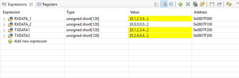
As you can see, i am not receiving any data in the second buffer.
As per understanding, after configuring the packets, like here in my case,
for channel 0, when it is triggered by the hardware request it has to automatically chained to the 3.
but seems it is not transferring the control to the other channel neiher for the transmission and reception. that is why i might not getting any data in the second spi buffer.
Can you please assist me in the same.
Regards,
Shivam Kakad
