Part Number: EK-TM4C1294XL
Tool/software: TI-RTOS
Dear Team,
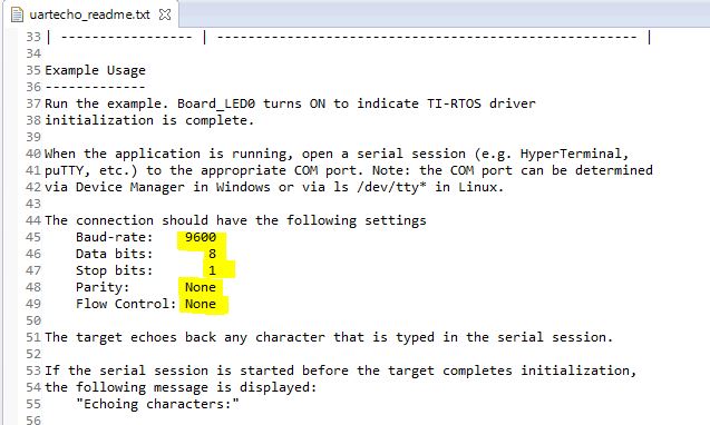
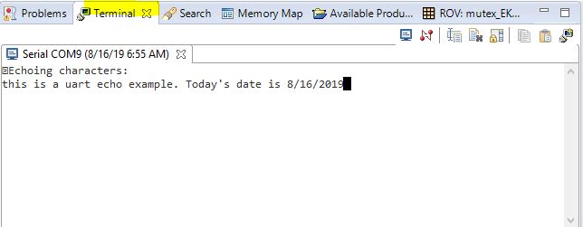
How to debug UART in UART echo example for EK-TM4C1294XL, UART echo example compiled & running, But how to check and debug that is send and receive data.
Thanks & Regards
Suresh
Original question:

Part Number: EK-TM4C1294XL
Tool/software: TI-RTOS
Dear Team,
How to debug UART in UART echo example for EK-TM4C1294XL, UART echo example compiled & running, But how to check and debug that is send and receive data.
Thanks & Regards
Suresh