This thread has been locked.

If you have a related question, please click the "Ask a related question" button in the top right corner. The newly created question will be automatically linked to this question.

TM4C1294KCPDT: TM4c1294 - USB CDC Communication event - USB_EVENT_DISCONNECTED not received

Part Number: TM4C1294KCPDT
Other Parts Discussed in Thread: EK-TM4C1294XL

TM4c1294 - USB CDC Communication event - USB_EVENT_DISCONNECTED not received

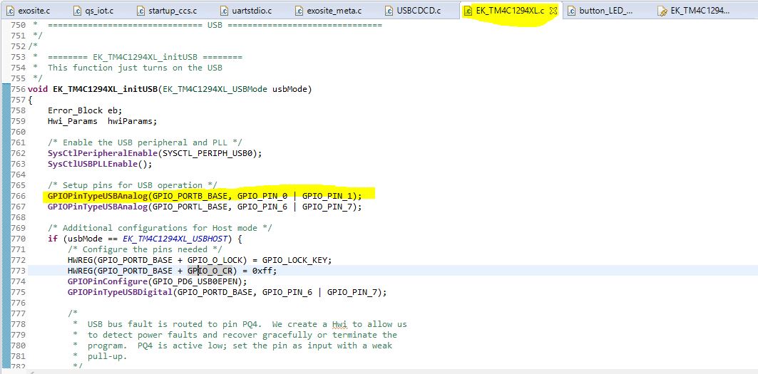
Reference : sample program provided. i.e usbserialdevice_EK_TM4C1294XL_TI.

It is observed that when the GPIO Board is connected to the Host, USB_EVENT_CONNECTED event is received.

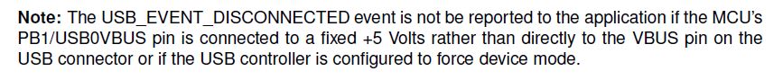
However, when the GPIO Board is disconnected from the Host, USB_EVENT_DISCONNECTED event is nor received in the GPIO board.

Kindly provide inputs on this.

  • Hi,

      Is GPIO board you own custom board? Do you have a TM4C129 LaunchPad board that you can run with the same sample program? Can you repeat the same issue?

  • Hi Charles,

    I have both custom board and TM4c1294 launchpad.

    In both the cases issue is seen. i.e DISCONNECT event is not received.

    Is it required to connect one of the pins to +5v(read this somewhere)

    Thanks,

    Jay

  • Hi,

     I read this from the USB library user's guide. 

    - Please check if you are connecting the VBUS on the USB connector to the PB1 pin directly. If not, you need to fix this on your board.

    - You need to configure the PB1 pin as the USB0VBUS pin rather than a GPIO pin. If you are using the sample example, I think this is already done. 

    - In the EK_TM4C1294XL.c file line 559, I think you should change from  USBStackModeSet(0, eUSBModeForceDevice, 0); to  USBStackModeSet(0, eUSBModeDevice, 0). When you are in Force Device mode, it does not monitor the VBUS.

      Please first make sure the above three instructions are met and first try on the launchPad. I just made the same change on the USBStackModeSet(0, eUSBModeDevice, 0) and run it on my launchPad and I can see USB_EVENT_DISCONNECTED received. 


  • Hi Charles,

    Thanks for the response.

    From the above 3 steps mentioned, could you please let me know more about the 2nd step.

    i.e You need to configure the PB1 pin as the USB0VBUS pin rather than a GPIO pin. If you are using the sample example, I think this is already done. 

    How to configure this?

    In the sample code where is it done?

    Thanks,

    Jay

  • Hi Jay,

      In the EK_TM4C1294XL.c file of the usbserialdevice_EK_TM4C1294XL_TI example, the PB1/PB0 are already configured as VBUS/ID pins. This is what I meant they are already done in the example. If you are creating a new USB project on your own in the future, please make sure this is done so that VBUS can be monitored by the USB device. 

  • Hi,

    One last query:

    - Please check if you are connecting the VBUS on the USB connector to the PB1 pin directly. If not, you need to fix this on your board.


    In the launchpad, is this already taken care? Or should we make this change of connecting the VBUS on the USB connector to the PB1 pin directly.


    Thanks.

  • Hi,

      In the launchPad the VBUS is already connected to the PB1 pn. You will need to do the same for your custom board. You can find the schematic of the LaunchPad board in the EK-TM4c1294XL User's guide. Below is the connection.

  • Hi Charles,

    Thanks for the reply.

    I have been told that in Custom board, this can be controlled via software, in the sense, without connecting VBUS to PB1 pin.

    Below is the snapshot from the document, 

    http://www.ti.com/lit/ug/spmu298d/spmu298d.pdf,

    So I assume with above configuration, can be alternative. 

    Please provide your thoughts on this.

    Thanks,

    Jay

  • Hi Jay,

      Yes, your understanding is correct that you can route the VBUS input to other GPIO. Please see below note about VBUS in the TM4C129 system guideline app note. http://www.ti.com/lit/an/spma056/spma056.pdf. You can create a voltage divider to route the 5V VBUS to 3.3V GPIO input.

    4.3.1 USB Device Only
    For TM4C129x devices that are used in a device-only configuration, the only signal used in addition to
    USB0DM and USB0DP is USB0VBUS, which is located on port PB1. PB1 is 5-V tolerant. In USB deviceonly
    mode, USB0VBUS is used to detect when voltage has been applied to or removed from the USB
    connector, which triggers software to manage the internal USB PHY accordingly.
    For a USB device-only configuration, a 100Ù resistor should be placed in series between VBUS on the
    USB connector and PB1 (or alternate GPIO) on the microcontroller in order to limit damage caused by any
    ESD events.

    If PB1 must be used for a function other than USB0VBUS, any other available GPIO could be used in its
    place. Because no other GPIO pins are 5V tolerant, a 5.6KÙ +/- 5% in series with a 10KÙ +/- 5% resistor
    should be wired as a voltage divider between VBUS on the connector and ground. This circuit drops the
    5V VBUS value to 3.2V at the GPIO pin.

  • Hi Charles,

    I have one quick question on this.

    Is it possible to get this DISCONNECT event without connecting any external resistor?

    I mean with only software configuration and not connecting external resistors? (Hardware change related to connecting/reconnecting any existing resistor is OK)

    At this point of time it is difficult for us to have an additional hardware in the project.

    Thanks,

    Jay

  • Hi Jay,

      I'm not sure what USB mode you will be operating under. In your prior post you were asking if you could use other GPIO pins to monitor the VBUS. If this is the case, you must use resistor divider. The TM4C129 is not 5V tolerant. You will damage the device if you feed a 5V input to any IO pins except the PB1. If you are operating in USB device-mode only then you can connect the VBUS to PB1 via a 100ohm resistor in series. Otherwise, you risk having the ESD failure.  However, if you intend to the USB OTG mode then you must connect the VBUS to the PB1 directly without any resistor. Please refer to the TM4C129 system design guideline. Below is the excerpt about the OTG mode. 

    'To support full USB OTG negotiation using the SRP and HNP protocols, VBUS from the USB connector
    must be directly connected to USB0VBUS(PB1) of the microcontroller without a series resistor in between.
    In this case, USB0VBUS should be connected to an ESD suppressor such as a TVS diode, or ESD
    resistant VBUS switch.'

  • Hi Jay,

    I had past noticed the same issue with launch pad not indicating disconnect via VBUS (PB1) was also software related. After minor modification it detects every time now. This switch was uint32_t and seems to work better as volatile Boolean. However if PB1 has been stressed it may not help to modify the switch. PB1 should have a  high kilO/megO (ohmic) reading/s and may fail to detect cable disconnect if lower than 250 ohms.

    //*****************************************************************************
    //
    // Global flag indicating that a USB configuration has been set.
    //
    //*****************************************************************************
    static volatile bool g_bUSBConfigured = false;

        //
        // Which event are we being sent?
        //
        switch(ui32Event)
        {
            //
            // We are connected to a host and communication is now possible.
            //
            case USB_EVENT_CONNECTED:
            {
                g_bUSBConfigured = true;
                g_ui32Flags |= COMMAND_STATUS_UPDATE;
    
                //
                // Flush our buffers.
                //
                USBBufferFlush(&g_sTxBuffer);
                USBBufferFlush(&g_sRxBuffer);
    
                break;
            }
    
            //
            // The host has disconnected.
            //
            case USB_EVENT_DISCONNECTED:
            {
    
                g_bUSBConfigured = false;
                g_ui32Flags |= COMMAND_STATUS_UPDATE;
    
                //
                // Flush our buffers.
                //
                USBBufferFlush(&g_sTxBuffer);
                USBBufferFlush(&g_sRxBuffer);
    
                break;
            }