This thread has been locked.

If you have a related question, please click the "Ask a related question" button in the top right corner. The newly created question will be automatically linked to this question.

TM4C1294NCPDT: A question of used the FP0 and PF4 as normal output GPIOs to control D4 and D3 to on/off on the TI TM4C1294NCPDT board.

Part Number: TM4C1294NCPDT

Hi, TI teams,

I use the  TM4C1294 Connected Launchpad (EK-TM4C1294XL) to do same experiments.

I use the FP0 and PF4 as normal output GPIOs to control D4 and D3 to on/off on, as below,

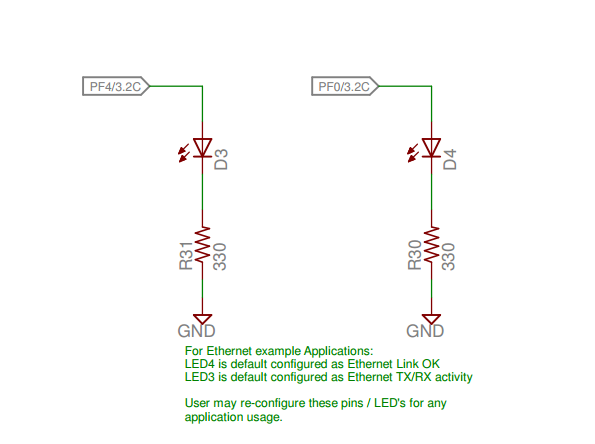
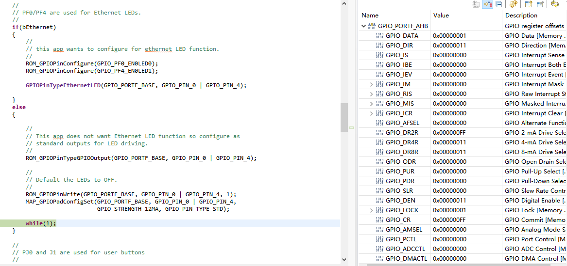
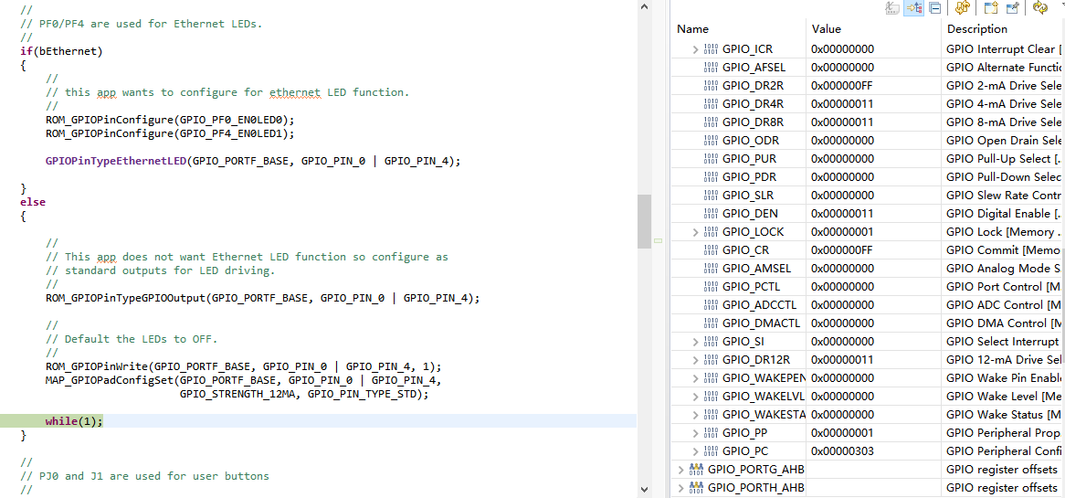
I modify the code in pinout.c, I write the PF0 and PF4 to 1, the D4 is lighting, but the D3 is not lighting, the code as below,

I read the TM4C1294 Datasheet, it is no ploblem about the code.

why the D3 is not lighting?

Regards,

eric

  • Hi,

      You should change:

    FROM:

    ROM_GPIOPinWrite(GPIO_PORTF_BASE, GPIO_PIN_0 | GPIO_PIN_4, 1);

    TO:

    ROM_GPIOPinWrite(GPIO_PORTF_BASE, GPIO_PIN_0 | GPIO_PIN_4, GPIO_PIN_0 | GPIO_PIN_4);

    Please note that the pins are specified using a bit-packed byte. What you wrote only sets PF0, not PF4. If you want to set both PF0 and PF4 you need to write 0x11, not 0x1.