This thread has been locked.

If you have a related question, please click the "Ask a related question" button in the top right corner. The newly created question will be automatically linked to this question.

Compiler/TM4C123GH6PM: can not produce outputs

Part Number: TM4C123GH6PM
Other Parts Discussed in Thread: EK-TM4C123GXL

Tool/software: TI C/C++ Compiler

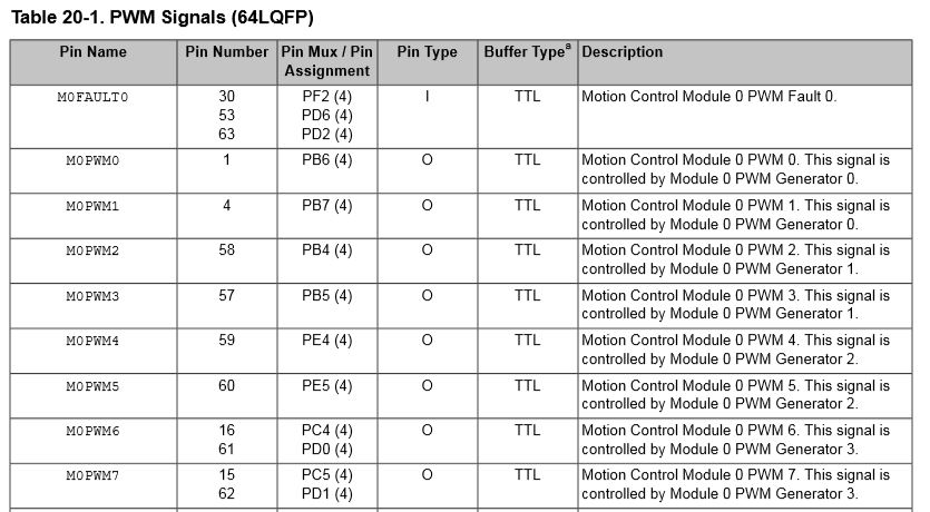
Our problem is that we can not get an output out of Pins:  61, 62, 63.

We are using a pulse-width modulator code to attempt to create a clock output.  The output should be a 0 to 3.3VDC square wave.

Pin 61 is a clock output, that output remains low.

Pin 62 and 63 also remain low.

We do have +3.3VDC at VDD and VBat pins.

  • Hi Robert,

     Can you please share your code? I think you might have missed some configuration. 

  • Failure to achieve MCU pin Output usually results from:

    • incorrect pin & port initialization (to include enabling, configuring & typing)
    • selecting pins which are 'not' GPIO and/or special output function capable

    You speak of 'Pulse-Width Modulator' code.   Had you noted that only a 'small set' of the MCU's GPIO pins may serve as, 'Official PWM Output Capable' pins?    Indeed - via software - you can induce most (any) pin to perform most (any) function - yet the 'special' PWM API functions address ONLY those pins which are truly PWM Designated!      

    Do pins 61, 62 & 63 meet those (strict) PWM capable requirements?

  • Charles,

    I need an email to send the files to, as I do not want to publicly send out our files.

    Please send your email to RLivsey@2quest.com.

  • As far as I can tell,  61,62, are capable.   Pin 61 is the pin that should have the pulse width modulator.

    please let me know how to send you the code.

  • Thank you - between vendor's Charles & outsider (moi) - we should quickly resolve your issue.

    When you 'registered' for the forum there was a 'checkbox' which (iirc) 'Enabled Conversations.'    Once checked - you can send & receive 'Private Messages' to other forum members.    (only those you specifically address)     

    Observe the 'top, right corner of this forum page' - you'll note 4 icons (which 'self-identify') when you 'mouse over.'    Second from left is the Message Selector - which you'll use (both) to Send & Receive.    Try that - my firm receives (near) immediate notification when such 'PM' arrives...

  • i sent 2 files to you using the private email in 2 separate emails

  • Thank you - it is a pleasure to deal w/forum user SO responsive!

    Staff just checked - they find pins 61 & 62 to be legitimate PWM Output Capable pins.    However pin 63 is a, 'PWM Fault Input Pin' (which KILLS those PWM outputs when 'active') and thus is UNSUITABLE for your PWM Output purposes!

    Our MCU manual - page1233 - reveals MANY potential, 'PWM Capable Pins' for your selection.    Avoid any of the 'PWM Fault Pins' - those are inappropriate for your expressed usage...

    *** 09:54 CST - no 'PM' has arrived!    You noted 2 'emails' - our preference (and only option) is for the 'PM' - as detailed in an earlier writing - this forum thread...   (our firm's email should (not) be visible and the nature of our work demands 'privacy' - thus my use of 'cb1' to comply w/regulators' dictates...)    

    Note that you WILL find it faster & easier to employ any of your MCU's Timer Pins - to produce a valid PWM Output.    These do NOT employ the PWM API functions - yet have been used successfully as PWM Generators many times - both by my firm & by (many) others.    You have substantial control of (both) the PWM Frequency AND Duty Cycle - although (some) custom software (relatively easy) is required.

  • I am using pin 62 as the PWM output.

    Does this mean that pin 61 can only be used as a PWM output and pin 63 can only be a PWM fault?

    I was trying to use  pins 61 and 63 as data lines (PDO and PD2 respectively), which are either a high or a low.

  • Hi Robert,

      Are you using the EK-TM4C123GXL launchPad? 

      The PD0 (pin61) and PD1 (pin62) on the J3 connector are connected to PB6 and PB7 respectively on the launchPad via a 0ohm resistor for some boosterpack compatibility reason. Please remove the R9 and R10 resistors. I think this is the problem. Hopefully this will resolve your problem if you are using the launchPad. If you have your custom board and still unable to generate PWM on PD0 and PD1 then it will be a different problem to investigate. 

    Hi cb1,

      Thank you for helping out this post. You are correct the pin63 is a fault input pin, not a PWM pin. 


  • The TM4C123GH6PM IC is mounted on a custom board.

    I am using the EK-TM4C123GXL launchPad for programming the IC only.

  • Kindly review our 'Cut/Paste' from the MCU manual.

    Note that pins 61 & 62 (PD0, PD1) - either or both - may be legitimately used as PWM outputs.

    Pin 63 - as the chart shows - may only be used as PWM Fault INPUT.    You MAY 'liberate' pin 63 from its 'PWM role' - and instead employ it as a GPIO input or output...

    Neither firm nor I have used this MCU recently enough to recall if 61/62 may 'divide' between: 'Use as PWM output (1 pin) AND GPIO Output (2nd pin.)

    Indeed - this is reasonably complex - but we've guided you as to how such 'Signal Pin Survey' may be conducted.   It does take time, effort & practice (primarily practice) to absorb this - and if you work in small, unrushed sessions - 'long-term' learning (even mastery) is likely to result.

  • Hi Robert,

      I created a sample program to produce PWM on the PD0 (pin 61) using M1PWM0. I run it on the launchPad. Please run it on your launchPad first and then run it on your custom board. If it works on the launchPad but not your custom board then it is likely a board problem. You might want to check for soldering and if good contacts on these pins. 

    pwm_invert_PD0_M1PWM0.zip

  • Hi Robert, Carl,

      Here is the project again. Please let me know if you can download it. 6283.pwm_invert_PD0_M1PWM0.zip