This thread has been locked.

If you have a related question, please click the "Ask a related question" button in the top right corner. The newly created question will be automatically linked to this question.

TM4C1294KCPDT: PCB design constraints

Part Number: TM4C1294KCPDT
Other Parts Discussed in Thread: LM3S6965

Hi,

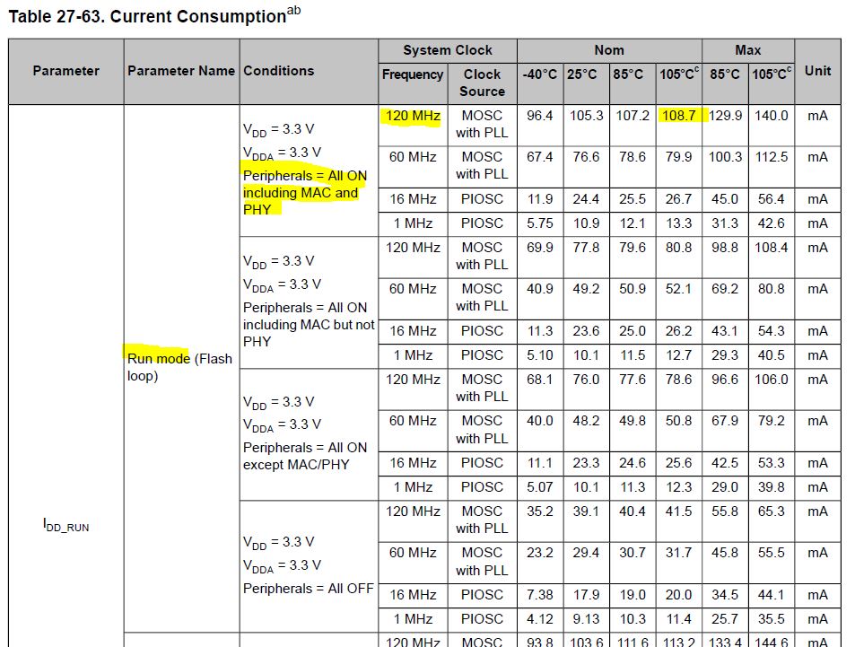
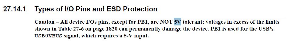
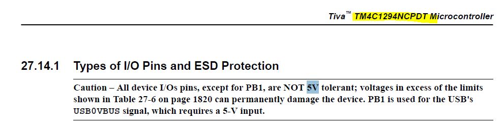
we are selecting TM4C1294KCPDT controller for our new project instead of LM3s6965
we are planning to design two PCBS for our system
1. PCB 1 will have microcontroller, crystal, ethernet RJ 45 connector, RTC, EEPROM, SD card on the board
2. PCB 2 will have other components like TFT display, LEDS, RS485, Relays, DAC

Please guide us if such system will work properly.
or we need to take care anything to pass type testing like EMI testing issues.

Is it required to keep i2c and spi peripherals on the micro controller board ?
or
Is it possible to keep SPI peripheral like SD card, DAC on another board?

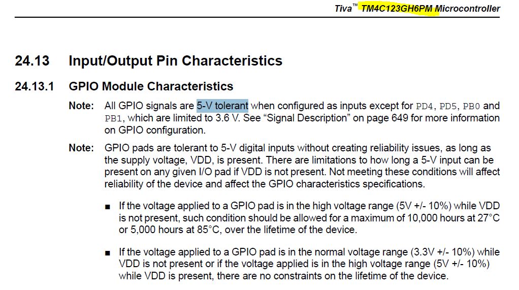
In our earlier system we use LM3S6965 controller, In that we use RTC 8583 with I2c interface we use onboard I2c 

We faced problem that in certain power on I2c SDA pins remains low and we get RTC Fail error. so considering above issue


Please guide us which components we need to keep near to the controller while doing PCB design so that our type testing will be successful.


Regards,

Anushka

  • HI Anushka,

      Thank you for migrating to the TM4C129 MCU as LM3S6965 is a categorized as NRND in ti.com. I don't see a problem with your system requirement. One note is that there is a built-in RTC module in the TM4C MCU. As far as PCB design, there is a TM4C129 system design guideline that should answer most of your questions. Please see below link to the document. 

    http://www.ti.com/lit/an/spma056/spma056.pdf

    As far as keeping i2c and spi peripherals on the board, it is your application that shall determine the usage/need of these peripherals. I've not come across the issue you mentioned with the i2c in the TM4C129 MCU. Please do go through the TM4C129 errata for the modules that you will be using in your application. 

  • Vendor's Charles provides his (usual) sage advice - best for you to follow his direction.

    Anushka Parab21 said:
    1. PCB 1 will have microcontroller, crystal, ethernet RJ 45 connector, RTC, EEPROM, SD card on the board
    2. PCB 2 will have other components like TFT display, LEDS, RS485, Relays, DAC

    In your unique, 2 or multi-board design, may we suggest the following:

    • when & where the MCU Board (Bd. 1) will 'feed' the Accessory Board (Bd. 2) it proves wise to group & run the MCU signals to a, 'board-edge header.'   In some cases - it may prove best to employ one or several buffer ICs - which protect the MCU & may provide 'signal boosting' - insuring proper board to board signal levels.   (and ESD resistance)
    • critical & low-level signals - travelling between boards - should be painstakingly routed - likely 'guard-banded' by surrounding these signal traces w/ground traces - and routed as directly as possible to board edge header(s).    No high-speed, high current or noise generating signals should be allowed (nearby) or run parallel to such critical signals.
    • if those critical signals are low-level - it may prove wise to, 'Amplify them upon board n' (n>1) - prior to sending them along to board 1.
    • it is always wise to provide for 'future & expanded needs' - with adequate forethought one can avoid a 'board-spin' - by providing 'extra 'MCU GPIO & Peripheral' pins - routed (again) to board-edge headers.    Even if 'not needed now' - especially if 'not needed now' - those extra pin accommodations will prove their, 'Weight in Gold' - downstream...
    • we always provide several 'monitor Leds' on the MCU board enabling general (even specific) diagnostics - and even a serial port for a character Lcd - to further 'ease, speed & detail/instruct' board operation & performance.

    One can (never) provide 'too many': 

    • added/spare pin functions
    • well-considered & convenient pcb signal routings
    •  and 'on-board' diagnostic capabilities

    The time, cost & effort (later) 'Saved' due to this Board planning & execution - will prove worth its weight in Silver (at least) ... Gold (more likely!)

  • Hi cb1,

    "LIKE"... I wish the "LIKE" button resurrected. 

  • Charles Tsai said:
    "LIKE"... I wish the "LIKE" button resurrected. 

    Hello my (properly wishful) friend, Charles!     Humble/feeble 'outsiders' - seeking to generate (some slight) incentive/positive feedback - continue to 'Bang their heads against the stone wall.'    And somewhere - a marketing textbook will (surely) note the 'unique promotion' of MCUs - by referring to them (only) as 'other!'

  • As in the datasheet of the controller specifies max operating voltage is 0 to 4V

    So are the GPIO pins 5V tolearnet?

    Can I directly connect RS485 IC which has operating voltage of 5V to the UART of the controller?

    Also Max current consumption of the IC is specified as 64mA?

    Does it change with crystal  Frequency?

    Regards,

    Anushka

  • Anushka Parab21 said:

    Also Max current consumption of the IC is specified as 64mA?

    Does it change with crystal  Frequency?   

    If you are (really) asking about 'Crystal's Frequency' - rather than the 'System Clock's Frequency' - my firm has noted:  (as regards MCU's current demand)

    • if/when 'not' deploying the PLL (thus relying upon the external xtal for 'System Clock generation') current level rises w/the xtal's frequency

    But - should you be seeking, 'MCU's current demands vs. System Clock':

    • higher frequency crystals require 'fewer MCU multiplication steps/elements' - to produce far higher frequency PLL clock rates
    • it was thus believed that, 'Higher frequency xtals' would 'reduce MCU  current demand'

    However our 'real-world' experiments 'did not (notably) 'bear this out.'    (measured current appeared 'reasonably' flat-lined - independent of  '4:1' xtal frequency change!     (same xtal vendor (intact xtal bypass caps) for each test)

    To your, "Are GPIO pins 5V tolerant?"     MCU's GPIO Section (w/in data manual) along w/the GPIO Specs (very rear of that manual) reveal that such tolerance does exist - but for (a few) notable exceptions!    You must find - and comply with - those 'exceptions.'   

    In addition - care must be exercised should 'external signals' (still) arrive at the MCU - even when the MCU is 'unpowered.'     Users are informed/advised to employ (proper) current limiting resistors to 'protect' such pins - yet NO mention is made of (any) potential 'long term harm' - which may result from:

    • long-term continuation of such signals - while the MCU is unpowered
    • impact of 'multiple' such signals - again long-term & 'clustered' upon 'ONE SIDE' (the same side) of the MCU

    Those 'last two' prove (extremely difficult) to,  'Anticipate, Characterize and/or Measure!'      (thus are 'not' (properly - or at all) reflected w/in datasheets (here or elsewhere).   

    My Tech firm favors 'Disallowing the arrival' of such signals - when the MCU is unpowered.     Multi-bit (pin) buffers - imposed between the MCU & the 'outside world' - effectively 'gate' such external signals.    Such appears to have (thus far) 'Prevented MCU Damage' - which past was 'notable' - when these external signals passed long-term, 'unmanaged!'     (while 'anecdotal' - 'Safe trumps Sorrow' - and 'Risk-Reward' runs (much) in favor of this/similar 'protective technique!')

  • Anushka Parab21 said:

    As in the datasheet of the controller specifies max operating voltage is 0 to 4V

    So are the GPIO pins 5V tolearnet?

    The MCU you are migrating to is TM4C1294KCPDT which is not 5V tolerant. You must obey the IO limitation specified in the TM4C1294KCPDT datasheet and use level shifter to interface to external components that are not 3.3V.  The TM4C123 family is 5V tolerant. However, it doesn't not meet your system requirements as it does not have Ethernet and other peripherals which are available in the TM4C129.

    Anushka Parab21 said:

    Also Max current consumption of the IC is specified as 64mA?

    Does it change with crystal  Frequency?

    Thank you, cb1 for providing much of the answers. 

    Anushka, can you tell me from which operating condition under which the MCU will consume 64mA in the datasheet? The current consumption shown in the datasheet depends on which operating conditions the MCU is operating in such as frequency, temperature and operating mode (run, sleep, deep sleep). If you are running at 120MHz with all the peripherals turned ON at 105 degree with nominal process it could be up to 108mA. 

  • Greetings Charles,

    Thank you - yet may staff & I note our 'discomfort' in learning that (some) TM4C129 devices (well preferred to 'other') MCUs   "Do Not Support '5V Tolerance' upon many/most of their GPIO pins!"     From staff's & my time here (near considerable) the impression gleaned was, 'Just as we earlier noted - "that only a 'marked few such GPIO' proved '5V intolerant."     Thus our surprise.

    May it be noted that (most all) competing ARM Cortex M4-class MCUs do sport 5V tolerance.    It thus is wondered - 'How & Why' - poster's specific MCU 'denied that 5V tolerance?'      Might you, 'take a shot' in explanation?

    We remain 'Cautious & Wary' of such tolerance - especially so when such external signals may prove 'long-term' - and persist even when - and especially when - the MCU becomes unpowered!

    May we note that 'other' rises again - in describing 'most of your M4 MCUs  '5V tolerance' - but for (an assumed few) 'others!'

  • Hi cb1,

     There is only one pin in the TM4C129 that is 5v tolerant which is the PB1 pin. The PB1 pin must be 5V tolerant as it is used to monitor the USB VBUS input in OTG mode. I don't have the history as to why TM4C129 was designed to not support 5V tolerant. It is a marketing decision. For output, it is not 5V capable and you will still need level translator to interface with 5V components. In other TI MCU that I'm familiar with, they are generally 3V capable only but ADC inputs are exception to support 5V input.  

    As you very well noted, even with 5V tolerant I/Os as in TM4C123, 5V input on the GPIO while the device is unpowered should be avoided or at least confined to the duration of such occurrences as specified in the datasheet . Please see below note in the TM4C123 datasheet.


  • Charles,

    Thank you - 'Crack of the bat response' - and 'loaded' w/useful comment.

    We (must) ask: is it proper for us to 'highlight' a (rather clear) CONFLICT w/in the presented 'datasheet extract!'

    Conflict follows:

    27.14.1   All device I/O pins, except for PB1, are NOT 5V tolerant.

    And this is (very) shortly followed by: "All GPIO signals are 5-V tolerant  when configured as inputs!"    (this from your 1st Note)

    And then - reinforcing the above - "GPIO pads are tolerant to 5-V digital inputs  without creating reliability issues"   (this from your 2nd Note)

    Might you review & 'inform/advise?'     (we've added 2nd/3rd 'line' - to prevent the wildly flapping, 'Conflict Pennant' - from becoming 'Lost at Sea.')

  • Hi cb1,

      Sorry for the confusion. The first note was taken from the TM4C129 datasheet while the second note was from the TM4C123 datasheet. I recapture the notes in the below two screenshots. Hope it will clarify. 

    In TM4C129 Datasheet:

    In TM4C123 Datasheet:

  • Hi Charles,

    Aha - NOW that's understandable.    Conflict resolved.

  • As we are replacing our controller LM3S6965 with TM4C129KCPDT 

    Please let us know the launch date of the controller.

    Regard,

    Anushka

  • Hi Anushka,

      The TM4C129x family MCU has been in production for many years. What do you mean by launch date?

  • Charles Tsai said:
    What do you mean by launch date?

    Would not poster have received an 'equally correct' response ... by requesting 'expiration date?'     {kidding...}

    Rarely does a Tech Forum 'announce' New Product Arrivals...

  • I want to know the first production date of the TM4C1294KCPDT controller.

    Regards,

    Anushka

  • Anushka Parab21 said:
    I want to know the first production date of the TM4C1294KCPDT controller.

    My friend -  vendor Charles has clearly noted that the MCU has, "LONG been in existing production!"     The 'launch date' has LONG PASSED...

    (should you have (some) reason to 'know' the actual (again long past) 'Initial date of first production' - that's a task for vendor agents.)

  • I mainly concern about the life cycle of the device

    as we are going to change this controller in almost all in our product and we want minimum 10 years of retention.

    that's why i am asking 

    else suggest latest controller with on chip ethernet connectivity.

    regards,

    Anushka

  • Anushka Parab21 said:
    I mainly concern about the life cycle of the device

    Aha -  only now can I see the 'reason' for your question re: 'MCU's Launch Date and/or First Production Date.'     You may note that vendor's Charles - and I - failed to absorb your intent.   (meaning)

    Staff & I (we are outsiders) have 'many times' noted vendor agents here, 'assuring the forum' that the TM4C family will continue 'long term.'    In fact Charles stated just that - earlier right here - did he not?

    Employing the "Launch Date" as a, 'Valid & Exacting Prediction Tool'  (able to critically identify a device's 'EOL') - may prove, 'Not as exacting as you hope.'

  • Hi Anushka,

      I certainly do think the TM4C129 family will have many years to stay, hopefully longer than what you are asking. Many of the TI MCU are in production for longer than 10 years. But I can't personally guarantee xyz number of years. I think it is best for you to contact your local TI sales office and I believe they will be able to provide this information more conveniently than in the forum.