This thread has been locked.

If you have a related question, please click the "Ask a related question" button in the top right corner. The newly created question will be automatically linked to this question.

TM4C123GH6PM: Interrupt priority in TM4C123

Part Number: TM4C123GH6PM


Hello,

I am trying to get the FXOS8700 accelmag and FXAS21002 gyro to work with the TM4C123 mcu. So far, I wrote the i2c driver, made the sensor initialize generating interrupts, and handle those interrupts and read data from i2c. What happens is, if I configure the code to work with only one sensor, it works, but if I have two interrupts, after a while (like 30-60seconds) one of the interrupt handling mechanisms fail.

Here are the relevant parts of the code:

    // gyro interrupt pin setup
    SysCtlPeripheralEnable(SYSCTL_PERIPH_GPIOC);
    GPIOPinTypeGPIOInput(GPIO_PORTC_BASE, GPIO_PIN_4);
    GPIOPadConfigSet(GPIO_PORTC_BASE, GPIO_PIN_4, GPIO_STRENGTH_2MA, GPIO_PIN_TYPE_STD);
    GPIOIntDisable(GPIO_PORTC_BASE, GPIO_PIN_4);
    GPIOIntClear(GPIO_PORTC_BASE, GPIO_PIN_4);
    GPIOIntRegister(GPIO_PORTC_BASE, gyro_isr);
    GPIOIntTypeSet(GPIO_PORTC_BASE, GPIO_PIN_4, GPIO_FALLING_EDGE);
    GPIOIntEnable(GPIO_PORTC_BASE, GPIO_PIN_4);

    // accelmag interrupt pin setup
    SysCtlPeripheralEnable(SYSCTL_PERIPH_GPIOE);
    GPIOPinTypeGPIOInput(GPIO_PORTE_BASE, GPIO_PIN_2);
    GPIOPadConfigSet(GPIO_PORTE_BASE, GPIO_PIN_2, GPIO_STRENGTH_2MA, GPIO_PIN_TYPE_STD);
    GPIOIntDisable(GPIO_PORTE_BASE, GPIO_PIN_2);
    GPIOIntClear(GPIO_PORTE_BASE, GPIO_PIN_2);
    GPIOIntRegister(GPIO_PORTE_BASE, accelmag_isr);
    GPIOIntTypeSet(GPIO_PORTE_BASE, GPIO_PIN_2, GPIO_RISING_EDGE);
    GPIOIntEnable(GPIO_PORTE_BASE, GPIO_PIN_2);

PC4 is configured for a falling edge, and PE2 is  configured for rising edge, which are connected to the sensor board, and gyro is configured to generate active 0 output (for falling edge) and accelmag board is configured to generate active 1 output.

// gyro interrupt service routine
void gyro_isr(void) {
    if(GPIOIntStatus(GPIO_PORTC_BASE, false) & GPIO_PIN_4) {
        GPIOIntClear(GPIO_PORTC_BASE, GPIO_PIN_4);
        gyro_data_ready = true;
    }
}

// accelmag interrupt service routine
void accelmag_isr(void) {

    if(GPIOIntStatus(GPIO_PORTE_BASE, false) & GPIO_PIN_2) {
        GPIOIntClear(GPIO_PORTE_BASE, GPIO_PIN_2);
        accelmag_data_ready = true;
    }
}

Here are the interrupt handlers. They just mark a volatile boolean so that I can read the sensor from the main loop.

In my main loop, I check for these booleans anrd read data:

    while(1) {

        //current_time = nh.now();

        if(gyro_data_ready) {
            GyroGetData(FXAS21002C_ADDRESS, &gyroRD);
            gyro_data_ready = false;
        }

        if(accelmag_data_ready) {
            AGGetData(FXOS8700_ADDRESS, &accelRD, &magRD);
            accelmag_data_ready = false;
        }
    }

No matter what I tried, I could not get rid of this bug. The active high interrupt for the accelmag, gets stuck at 1, meaning that the sensor was not read (which would have cleared the interrupt on the sensor)

At the beginning I was thinking this was related to the FXOS8700 accelmag orFXAS21002 gyro sensor, but at this point I believe this is interrupt related. Somehow, the sensor rises interrupt line, but the interrupt does not trigger, because other interrupt is happening. To support this theory:

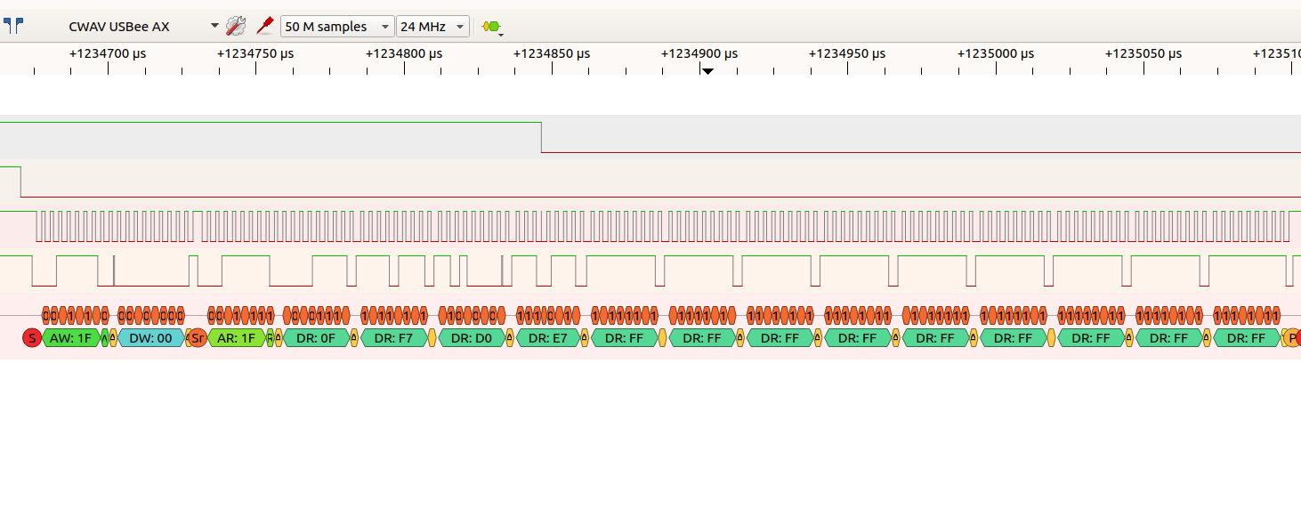
A. By examining the both interrupt lines with scope carefuly, (by videotaping it) I have evidence out that misfunction happens when two interrupts are triggered at the same time.

B. I replaced the failing accelmag interrupt from PE2 to PB4. This time the other interrupt line at PC4 fails (from the gyro)

Here is the link to the video:  twitter.com/altineller/status/1170381044115283973 (I had to put it on twitter because appearently vimeo does not like scope shoots)

Any ideas, help and recommendation on the problem greatly appreciated.

Best Regards,

Can

  • Hello cb1_mobile,

    I will try these as soon as possible. I already tried powering the board from a usb power bank, and the laptop disconnected from mains.

    The adafruit board has a mic5225 regulator. it is powered by usb vbus of the eval board. The usb does supply upto 2Amps. If I was powering the board from the 3V3 of the launchpad that could maybe drain the tps76333, but however, I will try powering the board with an adjustable lab supply and see what happens.

    "'Sensor Board provider's of 'voltage translators' as a (strong) candidate for 'glitching'  - when such 'push-pull' signal toggles!    And (that) is exactly when - the 'glitch appears upon posters (otherwise) pristine SCL signal line.     (the interrupt's "


    That part is very good. I did suspect the voltage translators, did not know why.. Thats a very good explanation.

    Also, when I switched to usbee ax to 24mhz capture, on the i2c decode, * in some of the fails * - it will show all tha packets as expected. but the i2c clock spike is there.

    Also, I changed the i2c reading statements from being within ISR's and put them in the main loop. With this setting one thing has changed. Either gyro or accelmag can fail in same fashion. Mostly accelmag sensor fails but sometimes the gyro fails, in the same fashion.

    Yes, I think this issue and mystery with the sensor has not been finished yet, but we can observe and replicate the fail, so the bug is "cornered"

    There is another version of the sensor board made by element14: element14.com/community/docs/DOC-75622/l/breakout-board-with-the-fxas21002c-and-the-fxos8700cq - it does not have voltage translators, or a onboard regulator, so I think it is more suitable.

    I am also considering just removing those mosfet voltage translators and pullup resistors

    Best regards,

    C.

  • Hello Can. My "final" proposal would be to use an I2C-to-Serial(RS-232/TTL) converter and loop-back the Tx pin of the serial edge to the Rx pin.

    So, whatever you send to the I2C bus of the MCU (try some test data also) it is eventually send back to your INT/reading routines on the MCU. If

    everything goes straight and correctly -no missing/fault readings, then use TWO(2) I2C-to-Serial converters, one pluged onto MCU's I2C bus and

    one onto sensor's I2C bus. Cross-wire then the two serial edges, Rx(s)-to-Tx(s). Let the game begin then. Power everything from the very same 

    source directly.  A good source for such converter may be this: https://www.sparkfun.com/products/retired/9981 or export.farnell.com and you get 

    everything within a couple of days.  These are cheap converters. That way I estimate that you/we-all eventually will identify the core source of the 

    problem. Keep us updated.

    John

  • can altineller said:
    I will try powering the board with an adjustable lab supply and see what happens.

    We believe that makes great sense - especially if the lab supply can supply 5V @ 2A or greater.    Proper power - and its distribution/delivery - is always 'Requirement #1.'

    The fact that the 'Glitch imposed upon SCL' occurs in coincidence w/the toggle (H -> L) of the sensor's interrupt - suggests:

    • a sensor issue
    • or a 'circuit difficulty' in accepting the 'strong/sudden' negative edge of the interrupt

    One of the easiest solutions is the imposition of a series resistor (1K - 2K2) between the sensor's 'int' pin & the MCU's receiving GPIO.    It cannot hurt to revisit the code which configures that GPIO - and insure that it has remained set as an input.   (I'd set its output current to the minimal value - just in case)

    The 2nd element of the 'solution' was the addition of a 100K pull-down R - placed upon the sensor's 'SCL' line.   (between the voltage translator & the sensor - NOT on the MCU side.)    The use of a small, ceramic bypass cap (0.005µF as a start) installed (very) close to the sensor's SCL pin - provides additional insurance.

    It is believed that the 'Ease, Speed (no shipping) & Cost' (less than low) of this method proves highly desirable...

  • Hello,

    I tried the following:

    a. inserting 2.2K, 4.7K, 10K between the mcu and interrupt outputs of the sensor: it did not crash for 10 minutes. I almost thought it was solved.

    b. configuring sensors with opendrain, and using pull up lines: same results as before, crashing before <10seconds to crash. [These were pulled up to the sensors side 3V3]

    c. pulling down SCL with 10K: same results as before <10 seconds to crash. [however,  this was pulled down from mcu side, I realized i did it wrong after seeing your last post.

    I also was not able to capture the fail in a. I might be able to devise a method for doing this. (triggering pulseview to stop recording, and just keep N datapoints and remove from the otherside)

    Tomorrow, I will visit my 'highly skilled' friend, and have the mosfets removed, as well as the pullup resistors with it, and just get rid of the voltagetranslator parts. Basically, I will have Q1,Q2,R3,R4 removed and have 2nd and 3rd pins of each Q1,Q2 soldered with a thin teflon wire, keeping R1 and R2 pulling up to sensor side 3v3. It will be a little frankenstein, but  the voltage translators are a big 'if' in the experiment - so i think best way of getting rid of them.

  • Thank you - let today's 'cross-exam' now begin:

    can altineller said:
    a. inserting 2.2K, 4.7K, 10K between the mcu and interrupt outputs of the sensor: it did not crash for 10 minutes. I almost thought it was solved.

    And did you know ... we 'heard' your 'primal screen' (from Turkey) all the way in USA's Chicago!    When this was done - were you (still) in default (Int as Push-Pull) Accel Mode?

    • is it 'true' - that your MCU is 3V3 powered from your LPad's linear regulator - while the accel sensor - is 3V3 powered from the sensor board's regulator?    That's NOT a good design practice.  (those different supplies are 'unlikely' to enjoy 'meeting.')  It would be 'highly useful' for you to observe the 'Int' line (scope please) during the 'H -> L' transition - it is suspected that (when 'Lock-Up' occurs)  this signal drives (below) ground - and may even 'ring.'
    • should such negative voltage swing be noted - install a Schottky diode - such that the negative voltage swing is clamped to a few hundred mV below ground.
    • in the event that a signal 'ring' is observed (yielding a voltage peak >3V3) - install a 2nd Schottky - such that the 'ring transient' is clamped to  a few hundred mV above 3V3.
    • belief continues that a 'ceramic bypass cap' - along w/~10K series R - placed as close as possible to sensor's SCL pin - may prove 'Eureka.'   (change the pull-down to the 'earlier' 100K suggested - not 10K)

    It has never been revealed if you:

    • placed the SCL line - traversing the MCU board to Sensor board - w/in a 'Shielded Cable.'
    • and moved the SCL wire - as far as possible from the 'signal pack' - to lessen the (expected) unwanted signal/spike coupling