This thread has been locked.

If you have a related question, please click the "Ask a related question" button in the top right corner. The newly created question will be automatically linked to this question.

TMS470MF06607: Boot loader and Application program start address @ 0x8000 not working

Part Number: TMS470MF06607
Other Parts Discussed in Thread: UNIFLASH, HALCOGEN

Hi…, 

We are developing a boot loader for TMS470MF06607 controller. We are using the example boot loader program from TI developed by Mr.QJWang.

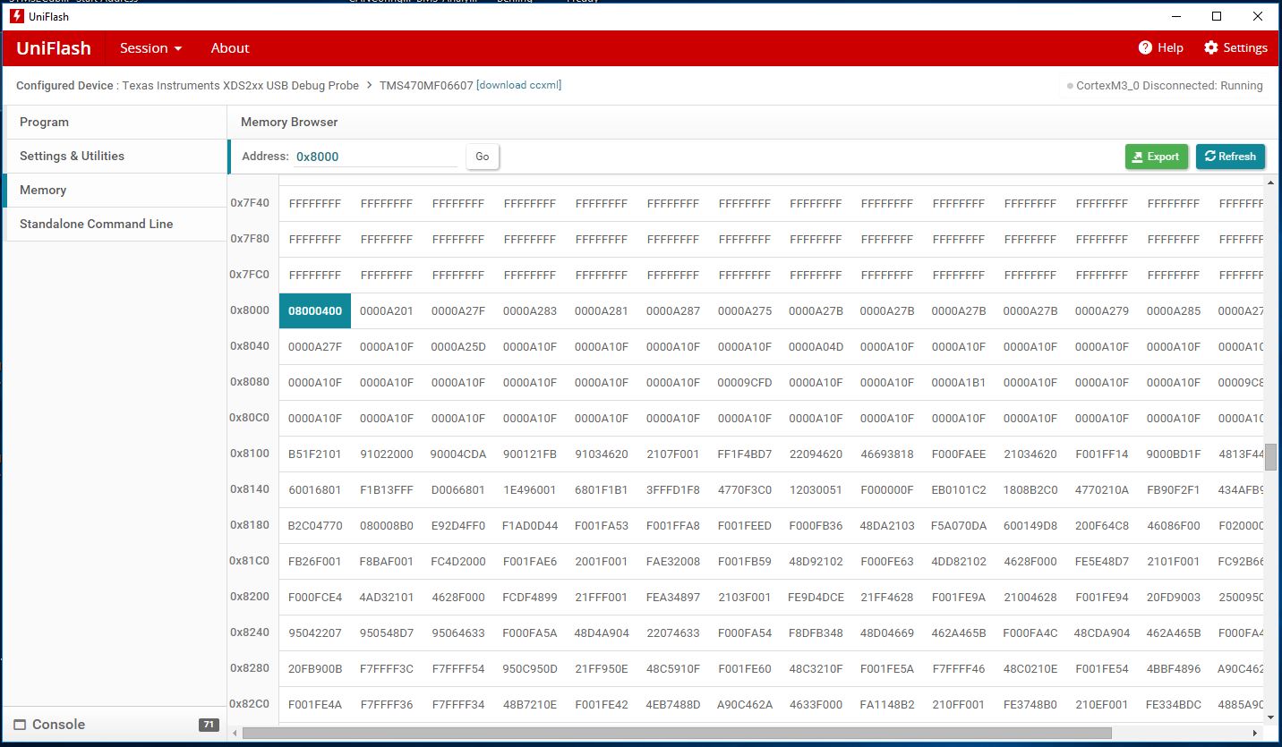
The boot loader is able to flash the application code to the designated Flash memory. We have confirmed this by reading the memory form controller using UniFlash software at boot loader address at 0x000 and application address at 0x8000. But after flashing when we try to run the application code it’s not running.

We need support to confirm whether we have done the memory mapping properly in the application program. I have attached the images of the memory map that we have done. We followed the application note SPNA200–September 2013 - CAN Bus Bootloader for TMS470M MCU for memory mapping of application program.

The application has to reside in the Sector 2 of Flash Bank0 @ 0x8000 address

Below is the Application Program Memory mapping:

/* Linker Settings                                                            */

-l rtsv7M3_T_be_eabi.lib

--retain="*(.intvecs)"

/* USER CODE BEGIN (1) */
/* USER CODE END */

/*----------------------------------------------------------------------------*/
/* Memory Map                                                                 */

MEMORY
{
    VECTORS (X)  : origin=0x00008000 length=0x00000100
    STACKS  (RW) : origin=0x08000000 length=0x00000800
    FLASH0  (RX) : origin=0x00008100 length=0x00077EFF+1
    FLASH1  (RX) : origin=0x00080000 length=0x0001FFFF+1
    RAM     (RW) : origin=0x08000800 length=0x0000F800

/* USER CODE BEGIN (2) */
/* USER CODE END */
}

/* USER CODE BEGIN (3) */
/* USER CODE END */

/*----------------------------------------------------------------------------*/
/* Section Configuration                                                      */

SECTIONS
{
    .intvecs : {} > VECTORS
    .text    : {} > FLASH0 | FLASH1
    .const   : {} > FLASH0 | FLASH1
    .cinit   : {} > FLASH0 | FLASH1
    .pinit   : {} > FLASH0 | FLASH1
    .bss     : {} > RAM 
    .data    : {} > RAM 
    .sysmem  : {} > RAM

   .stack   :                            /* SOFTWARE SYSTEM STACK                 */
   {                                                   /* initial stack pointer values          */
    . += 0x00000400;  _Stack_Table_Pointer  = .;
    . += 0x00000400;  _Stack_Handler_Pointer  = .;
   } > STACKS

/* USER CODE BEGIN (4) */
/* USER CODE END */
}

Below is the Boot Loader Program Memory mapping:
//*****************************************************************************
//
// bl_link.cmd : Define the memory, section, and section for flash API
// Author      : QJ Wang. qjwang@ti.com
// Date        : 5-9-2013
//
// Copyright (c) 2008-2011 Texas Instruments Incorporated.  All rights reserved.
// Software License Agreement
//
// Texas Instruments (TI) is supplying this software for use solely and
// exclusively on TI's microcontroller products. The software is owned by
// TI and/or its suppliers, and is protected under applicable copyright
// laws. You may not combine this software with "viral" open-source
// software in order to form a larger program.
//
// THIS SOFTWARE IS PROVIDED "AS IS" AND WITH ALL FAULTS.
// NO WARRANTIES, WHETHER EXPRESS, IMPLIED OR STATUTORY, INCLUDING, BUT
// NOT LIMITED TO, IMPLIED WARRANTIES OF MERCHANTABILITY AND FITNESS FOR
// A PARTICULAR PURPOSE APPLY TO THIS SOFTWARE. TI SHALL NOT, UNDER ANY
// CIRCUMSTANCES, BE LIABLE FOR SPECIAL, INCIDENTAL, OR CONSEQUENTIAL
// DAMAGES, FOR ANY REASON WHATSOEVER.
//
//*****************************************************************************

--retain="*(.intvecs)"


MEMORY
{
    VECTORS (X)      : origin=0x00000000 length=0x00000100
    FLASH_API  (RX)  : origin=0x00000100 length=0x00001500
    FLASH0  (RX)     : origin=0x00001600 length=0x0009EEFF
    STACKS  (RW)     : origin=0x08000000 length=0x00000B00
    SRAM    (RWX)    : origin=0x08000B00 length=0x0000F000

}
SECTIONS
{
    .intvecs : {} > VECTORS


    flashAPI :
    {
//     ..\Release\source\bl_flash.obj (.text)
     ..\Debug\source\bl_flash.obj (.text)
     --library= pf035a_api_eabi.lib      < setup_fsm.obj
                                          prog_data.obj
                                          verify_data.obj
                                          erase.obj
                                          issue_cmnd.obj
                                          get_timing.obj
                                          Fapi_PollFlashStatus.obj
                                          feed_dog.obj
                                          sector_select.obj
                                          blank.obj
                                          compact.obj
                                          > (.text)
    } load = FLASH_API, run = SRAM, LOAD_START(api_load), RUN_START(api_run), SIZE(api_size)

    .text    : {} > FLASH0
    .const   : {} > FLASH0
    .cinit   : {} > FLASH0
    .pinit   : {} > FLASH0
    .data    : {} > SRAM
    .bss     : {} > SRAM
    .sysmem  : {} > SRAM

   .stack   :
   {
    . += 0x00000A00;  __STACK_TOP  = .;
    . += 0x00000100;  _Stack_Handler_Pointer  = .;
   } > STACKS
}

Thanks and Regards,

Anand Kumar D

  • Your application code starts with vectors at 0x8000, but the link command file for the bootloader defines flash memory as starting at 0x1600 of length 0x9EEFF, (0x1600 to A04FF). This means your boot loader may spill into where you put the application. Did you mean to define FLASH0 for the bootloader as:

        FLASH0  (RX)     : origin=0x00001600 length=0x00006A00
    

    A common mistake made on bootloaders for the Cortex M3 is to forget that the reset vector (which in your case is at 0x8004) needs to be an odd address (address+1) because the M3 only executes the Thumb2 instruction set.

  • Hello Bob,

    Thanks for the reply...

    A common mistake made on bootloaders for the Cortex M3 is to forget that the reset vector (which in your case is at 0x8004) needs to be an odd address (address+1) because the M3 only executes the Thumb2 instruction set.

    How to change the reset vector address at 0x8004 to an odd address. Does this mean that i have to change the NVIC address of the application program which is currently configured at 0xE000E000U in sys_startup.c file

    #define NVIC  0xE000E000U

    If so what value should i define to NVIC.


    Thanks and Regards,

    Anand Kumar D

  • What I mean is that the value stored at location 0x00008004 should be an odd number. If you used the standard sys_intvecs.asm with the "_c_int00" symbol to create the .intvecs section of your application code, everything should work. Just use either UniFlash or CCS to read the values that were programmed into locaitons 0x00008000 (stack pointer) and 0x00008004 (start address plus 1).

  • Hello Bob,

    The application HAL was created with HALCoGen. The application works fine without boot loader at start address  0x00000000 but when i change the start address to 0x8000 it is not working. 

    ;-------------------------------------------------------------------------------
    ; import reference for interrupt routines
    ;/****************************************************************************/
    ;/* INTVECS.ASM - Cortex_M3 INTERRUPT VECTORS TABLE SETUP FILE               */
    ;/****************************************************************************/
    	.ref _Stack_Table_Pointer
    	.ref _c_int00
     	.ref _NMI
     	.ref _Hard_Fault
      	.ref _Memory_Management
      	.ref _Bus_Fault
      	.ref _Usage_Fault
      	.ref _Reserved
     	.ref _SVC_Call  	 	  	
      	.ref _Debug_Monitor
     	.ref _Pend_SV
      	.ref _SYSTICK
      	.ref esmLowInterrupt
      	.ref rtiCompare3Interrupt
      	.ref can1HighLevelInterrupt
      	.ref adcGroup1Interrupt
      	.ref can2HighLevelInterrupt
      	.ref Dummy_ISR
     
        .sect ".intvecs"
    	.word _Stack_Table_Pointer	; Address of the default stack on reset 
    	.word _c_int00				    ; Power-on or warm reset
    	.word _NMI					; Non Maskable Interrupt
    	.word _Hard_Fault			    ; Repeated or unhandlable fault
    	.word _Memory_Management	    ; MPU related fault
    	.word _Bus_Fault			    ; Memory address/data related fault
    	.word _Usage_Fault			; Undef. instruction or similar fault
    	.word _Reserved				; Reserved
    	.word _Reserved				; Reserved
    	.word _Reserved				; Reserved
    	.word _Reserved				; Reserved
    	.word _SVC_Call				; System call with SVC instruction
    	.word _Debug_Monitor  		; Non-halting debug monitor
    	.word _Reserved				; Reserved
    	.word _Pend_SV				; Software pendable service request
    	.word _SYSTICK				; System tick timer interrupt
    
    	.word _NMI     ; Channel 0 
    	.word Dummy_ISR   			    ; Channel 1 
    	.word esmLowInterrupt     ; Channel 2 
    	.word Dummy_ISR			        ; Channel 3 
    	.word Dummy_ISR			        ; Channel 4 
    	.word Dummy_ISR			        ; Channel 5 
    	.word Dummy_ISR			        ; Channel 6 
    	.word rtiCompare3Interrupt    ; Channel 7 
    	.word Dummy_ISR                 ; Channel 8 
    	.word Dummy_ISR                 ; Channel 9 
    	.word Dummy_ISR                 ; Channel 10 
    	.word Dummy_ISR                 ; Channel 11 
    	.word Dummy_ISR                 ; Channel 12 
    	.word Dummy_ISR                 ; Channel 13 
    	.word Dummy_ISR                 ; Channel 14 
    	.word Dummy_ISR                 ; Channel 15 
    	.word Dummy_ISR                 ; Channel 16 
    	.word Dummy_ISR                 ; Channel 17 
    	.word Dummy_ISR                 ; Channel 18 
    	.word Dummy_ISR                 ; Channel 19 
    	.word Dummy_ISR                 ; Channel 20 
    	.word Dummy_ISR                 ; Channel 21 
    	.word can1HighLevelInterrupt   ; Channel 22 
    	.word Dummy_ISR                 ; Channel 23 
    	.word Dummy_ISR                 ; Channel 24 
    	.word adcGroup1Interrupt   ; Channel 25 
    	.word Dummy_ISR                 ; Channel 26 
    	.word Dummy_ISR                 ; Channel 27 
    	.word Dummy_ISR                 ; Channel 28 
    	.word can2HighLevelInterrupt   ; Channel 29 
    	.word Dummy_ISR                 ; Channel 30 
    	.word Dummy_ISR                 ; Channel 31 
    	.word Dummy_ISR                 ; Channel 31
    	.word Dummy_ISR                 ; Channel 31
    	.word Dummy_ISR                 ; Channel 34
    	.word Dummy_ISR                 ; Channel 35
    	.word Dummy_ISR                 ; Channel 36
    	.word Dummy_ISR                 ; Channel 37
    	.word Dummy_ISR                 ; Channel 38
    	.word Dummy_ISR                 ; Channel 39 
    	.word Dummy_ISR                 ; Channel 40
    	.word Dummy_ISR                 ; Channel 42
    	.word Dummy_ISR                 ; Channel 42
    	.word Dummy_ISR                 ; Channel 43
    	.word Dummy_ISR                 ; Channel 44
    	.word Dummy_ISR                 ; Channel 45
    	.word Dummy_ISR                 ; Channel 46
    	.word Dummy_ISR                 ; Channel 47 
    

    /* Include Files */
    #include "sys_common.h"
    #include "system.h"
    #include "sys_vim.h"
    
    /* USER CODE BEGIN (0) */
    /* USER CODE END */
    
    typedef void (*handler_fptr)(const uint8 * in, uint8 * out);
    
    #pragma WEAK(__TI_Handler_Table_Base)
    #pragma WEAK(__TI_Handler_Table_Limit)
    #pragma WEAK(__TI_CINIT_Base)
    #pragma WEAK(__TI_CINIT_Limit)
    
    extern uint32 __TI_Handler_Table_Base;
    extern uint32 __TI_Handler_Table_Limit;
    extern uint32 __TI_CINIT_Base;
    extern uint32 __TI_CINIT_Limit;
    extern uint32 *   __binit__;
    
    #define NVIC  0xE000E000U
    
    /*------------------------------------------------------------------------------*/
    /* C auto-initialization 							*/
    void _init()
    {
    /* initialize copy table */
        if ((uint32 *)&__binit__ != (uint32 *)0xFFFFFFFFU)
        {
            extern void copy_in(void *binit);
            copy_in((void *)&__binit__);
        }
    
        /* initialize the C global variables */
        if (&__TI_Handler_Table_Base < &__TI_Handler_Table_Limit)
        {
            uint8 **tablePtr   = (uint8 **)&__TI_CINIT_Base;
            uint8 **tableLimit = (uint8 **)&__TI_CINIT_Limit;
    
            while (tablePtr < tableLimit)
            {
                uint8 * loadAdr = *tablePtr++;
                uint8 * runAdr  = *tablePtr++;
                uint8  idx     = *loadAdr++;
                handler_fptr   handler = (handler_fptr)(&__TI_Handler_Table_Base)[idx];
    
                (*handler)((const uint8 *)loadAdr, runAdr);
            }
        }
    }
    /*------------------------------------------------------------------------------*/
    
    /* USER CODE BEGIN (1) */
    /* USER CODE END */
    
    /*------------------------------------------------------------------------------*/
    /* Enable interrupt Handling in NVIC 		                       	*/
    void NVIC_enable()
    {
    	uint32 *SETINT0;  /* Irq 0 to 31 Set Enable Register	     	*/
    	uint32 *PRIOR0;	  /* Irq 0 to 3 Priority Register			    */
    	uint32 *PRIOR1;   /* Irq 4 to 7 Priority Register			    */
    	uint32 *SYSHDLR;  /* System Handler Control and State Register 	*/
    
    
    	SETINT0 	= (uint32 *)(NVIC + 0x100U);
    	PRIOR0 		= (uint32 *)(NVIC + 0x400U);
    	PRIOR1 		= (uint32 *)(NVIC + 0x404U);
    	SYSHDLR     = (uint32 *)(NVIC + 0xD24U);
    
    	*PRIOR0 	= 0x80a0c0e0U;
    	*PRIOR1 	= 0x00204060U;
    	*SYSHDLR    = 0x00070000U; 
    	*SETINT0 	= 0x000000FFU;
    	
    #if VIM_CONFIG	
    	vimCfg();	/* Configure M3VIM Channels properties */
    #endif
    
    #if (VIM_ENABLE_NESTED_INTERRUPTS  == TRUE)
    	nestEnable();
    #endif 
    }

    The value at 0x8004 is 0x01 

     TMS470_RTC_Test.rar

    I have attached my application project. Please have a look at the same and guide me where i am wrong.

    Thanks and Regards,

    Anand Kumar D

  • Hello Bob,

    I observed that the code is working fine at start address 0x8000 with and without boot loader when the all the interrupts are disabled. But when the interrupts are enabled it’s not working.

    How and where should I define the Vector table offset value.

    Thanks and Regards,

    Anand Kumar D

  • Yes, before enabling interrupts in the application write 0x00008000 to location 0xE000ED08.

  • Hello Bob,

    Thanks for your support. We finally got everything working. We followed the following.


    Jump from boot loader to app address:


    uint32 JumpAddress = *(uint32*)(APP_START_ADDRESS+4);

    ((void (*)(void))JumpAddress)();


    Jump from app to Boot loader:


    rtiStopCounter(rtiCOUNTER_BLOCK0);

    rtiStopCounter(rtiCOUNTER_BLOCK1);

    rtiDisableNotification(rtiCOMPARE3);

     _disable_IRQ();

     *(uint32*)0xE000ED08 = 0x00000000;

    systemREG->SYSECR = 0x8000;

    Thanks and Regards,

    Anand Kumar D