


Part Number: TMS570LC4357
Other Parts Discussed in Thread: HALCOGEN
Hi,
I am trying to implement DMA based receive of a block of CAN data, I have configured DCAN 1 for CAN transfer(which is working fine for functionalities other than DMA) and using DCAN 1 IF3 for receiving data by DMA.
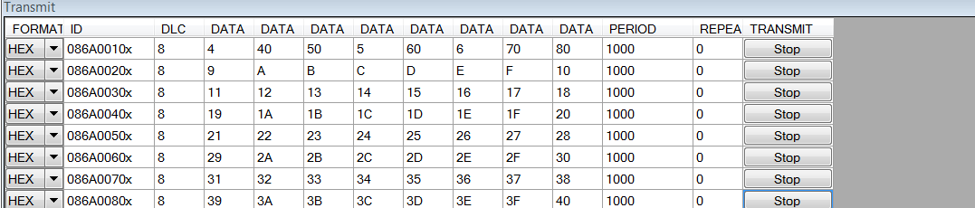
I have configured 8 mailboxes for the same and transmitting 8 can frames by Microchip CAN BUS analyser transmit features.
Below is my code for DMA with CAN-
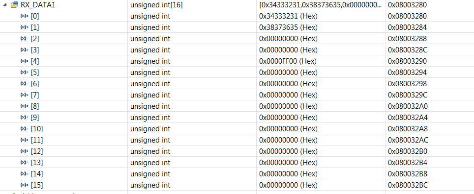
uint32 RX_DATA1[D_SIZE]= {0}; /* receive buffer in sys ram */
uint32 DMA_Comp_Flag;
g_dmaCTRL g_dmaCTRLPKT; /* dma control packet configuration stack */
main()
{
//can initialization functions
// IF3 configuration for DMA
//Enable DE3 bit in CTL register to trigger DMA when IF3 receives data
canREG1->CTL |= (1U << 20U);
// Read DATA A & B - 8 bytes */
canREG1->IF3OBS = 0x18;
// Message box 9-16 configured for auto update
canREG1->IF3UEy[0]= 0x0000FF00;
/* - DMA Configuration */
/* Enable DMA */
dmaEnable();
/* Enable Interrupt after reception of data */
dmaEnableInterrupt(DMA_CH0, FTC, DMA_INTA);
/* assigning dma request: channel-0 with request line - 16 ( DCAN1IF3) */
dmaReqAssign(DMA_CH0,16);
/* Reset the Flag */
DMA_Comp_Flag = 0xAAAA5555;
while(1)
{
dmaConfigCtrlRxPacket((uint32)(&(canREG1->IF3DATx[0])),
(uint32)(&RX_DATA1),
2); //element count
/* - setting dma control packets for transmit */
dmaSetCtrlPacket(DMA_CH0,g_dmaCTRLPKT);
// dmaEnable();
/* - setting the dma channel to trigger on s/w request */
dmaSetChEnable(DMA_CH0, DMA_SW);
/* Wait for the DMA interrupt ISR to set the Flag */
while(DMA_Comp_Flag != 0x5555AAAA);
/* Check the RX_DATA1 for the received message */
asm(" B $");
}
where :
void dmaConfigCtrlRxPacket(uint32 sadd,uint32 dadd,uint32 dsize)
{
g_dmaCTRLPKT.SADD = sadd; /* source address */
g_dmaCTRLPKT.DADD = dadd; /* destination address */
g_dmaCTRLPKT.CHCTRL = 1; /* channel control +1 */
g_dmaCTRLPKT.FRCNT = 8; /* frame count */
g_dmaCTRLPKT.ELCNT = dsize; /* element count */
g_dmaCTRLPKT.ELDOFFSET = 0; /* element destination offset */
g_dmaCTRLPKT.ELSOFFSET = 0; /* element source offset */
g_dmaCTRLPKT.FRDOFFSET = 0; /* frame destination offset */
g_dmaCTRLPKT.FRSOFFSET = 0; /* frame source offset */
g_dmaCTRLPKT.PORTASGN = 4; /* port b */
g_dmaCTRLPKT.RDSIZE = ACCESS_32_BIT; /* read size */
g_dmaCTRLPKT.WRSIZE = ACCESS_32_BIT; /* write size */
g_dmaCTRLPKT.TTYPE = FRAME_TRANSFER ; /* transfer type */
g_dmaCTRLPKT.ADDMODERD = ADDR_INC1; /* address mode read */
g_dmaCTRLPKT.ADDMODEWR = ADDR_INC1; /* address mode write */
g_dmaCTRLPKT.AUTOINIT = AUTOINIT_OFF; /* autoinit */
}
void dmaGroupANotification(dmaInterrupt_t inttype, uint32 channel)
{
DMA_Comp_Flag = 0x5555AAAA;
}
other functions are generated from halocgen where i have enabled the interrupt for DMA BTC and FTC and CAN 1 IF3 along with other CAN1 High and CAN1 Low interrupts.
With the above code I am having 2 problems-
1.If i give a free run or a step over command, the code gets stuck in phantom interrupt but I am able to run the code with step into commands.
2. Even when the code runs, I am getting data from only one of the frame (8 bytes) and that too in some different order which gives me a signal that there's something wrong with endianess however I have not changed any addresses manually and it is all generated by halcogen and working fine for features other than DMA.
I have attached the image of transmitted and received data.
can you please help me identify the issue and also suggest me the possible solution for the same?
Thanks
Archana
