Hi,
I am transmitting multiple CAN messages with different ID and try to receive only particular CAN message with a particular CAN ID. Can able to transmit multiple messages with different ID. but while receiving I cant able to receive the desired CAN message with a particular CAN ID. Plz help
Transmitter Code:
#include <stdbool.h>
#include <stdint.h>
#include <math.h>

#include "inc/hw_memmap.h"
#include "inc/hw_types.h"
#include "inc/hw_can.h"
#include "inc/hw_ints.h"
#include "driverlib/can.h"
#include "driverlib/interrupt.h"
#include "driverlib/sysctl.h"
#include "driverlib/gpio.h"
#include "driverlib/uart.h"
#include "driverlib/pin_map.h"

#include "utils/uartstdio.h"


volatile bool errFlag = 0; // transmission error flag
unsigned int sysClock; // clockspeed in hz

void delay(unsigned int milliseconds) {
   SysCtlDelay((sysClock / 3) * (milliseconds / 1000.0f));
}

// CAN interrupt handler
void CANIntHandler(void) {

   unsigned long status = CANIntStatus(CAN1_BASE, CAN_INT_STS_CAUSE); // read interrupt status

   if(status == CAN_INT_INTID_STATUS) { // controller status interrupt
      status = CANStatusGet(CAN1_BASE, CAN_STS_CONTROL); // read back error bits, do something with them?
      errFlag = 1;
   } else if(status == 1) { // message object 1
      CANIntClear(CAN1_BASE, 1); // clear interrupt
      errFlag = 0; // clear any error flags
       }
   else if(status == 2) { // message object 1
         CANIntClear(CAN1_BASE, 2); // clear interrupt
         errFlag = 0; // clear any error flags
          }
   else if(status == 3) { // message object 1
         CANIntClear(CAN1_BASE, 3); // clear interrupt
         errFlag = 0; // clear any error flags
          }
   else { // should never happen
      UARTprintf("Unexpected CAN bus interrupt\n");
   }
}

int main(void) {

   tCANMsgObject msg1,msg2,msg3; // the CAN message object
   unsigned int msg1Data, msg2Data, msg3Data; // the message data is four bytes long which we can allocate as an int32
   unsigned char *msg1DataPtr = (unsigned char *)&msg1Data;
   unsigned char *msg2DataPtr = (unsigned char *)&msg2Data;
   unsigned char *msg3DataPtr = (unsigned char *)&msg3Data;

   // Run from the PLL at 120 MHz.
   sysClock = SysCtlClockFreqSet((SYSCTL_XTAL_25MHZ | SYSCTL_OSC_MAIN | SYSCTL_USE_PLL | SYSCTL_CFG_VCO_480), 120000000);

   // Set up debugging UART
   SysCtlPeripheralEnable(SYSCTL_PERIPH_GPIOA); // enable UART0 GPIO peripheral
   SysCtlPeripheralEnable(SYSCTL_PERIPH_UART0);
   GPIOPinConfigure(GPIO_PA0_U0RX);
   GPIOPinConfigure(GPIO_PA1_U0TX);
   GPIOPinTypeUART(GPIO_PORTA_BASE, GPIO_PIN_0 | GPIO_PIN_1);
   UARTStdioConfig(0, 115200, sysClock); // 115200 baud

   // Set up CAN1
   SysCtlPeripheralEnable(SYSCTL_PERIPH_GPIOB); // enable CAN1 GPIO peripheral
   GPIOPinConfigure(GPIO_PB0_CAN1RX);
   GPIOPinConfigure(GPIO_PB1_CAN1TX);
   GPIOPinTypeCAN(GPIO_PORTB_BASE, GPIO_PIN_0 | GPIO_PIN_1);
   SysCtlPeripheralEnable(SYSCTL_PERIPH_CAN1);
   CANInit(CAN1_BASE);
   CANBitRateSet(CAN1_BASE, sysClock, 500000);
   CANIntRegister(CAN1_BASE, CANIntHandler); // use dynamic vector table allocation
   CANIntEnable(CAN1_BASE, CAN_INT_MASTER | CAN_INT_ERROR | CAN_INT_STATUS);
   IntEnable(INT_CAN1);
   CANEnable(CAN1_BASE);

   // Set up msg object
   msg1Data = 0;
   msg1.ui32MsgID = 1;
  // msg1.ui32MsgIDMask = 0;
   msg1.ui32Flags = MSG_OBJ_TX_INT_ENABLE;
   msg1.ui32MsgLen = sizeof(msg1DataPtr);
   msg1.pui8MsgData = msg1DataPtr;

   msg2Data = 0;
    msg2.ui32MsgID = 2;
   // msg2.ui32MsgIDMask = 0;
    msg2.ui32Flags = MSG_OBJ_TX_INT_ENABLE;
    msg2.ui32MsgLen = sizeof(msg2DataPtr);
    msg2.pui8MsgData = msg2DataPtr;

    msg3Data = 0;
     msg3.ui32MsgID = 3;
    //msg3.ui32MsgIDMask = 0;
     msg3.ui32Flags = MSG_OBJ_TX_INT_ENABLE;
     msg3.ui32MsgLen = sizeof(msg3DataPtr);
     msg3.pui8MsgData = msg3DataPtr;

   unsigned int t = 0; // loop counter
   float freq = 0.3; // frequency scaler

   while(1)
   {

         	        msg1DataPtr[0] = 0x01;
	   		msg1DataPtr[1] = 0x04;
	   		msg1DataPtr[2] = 0x03;
	   		msg1DataPtr[3] = 0x04;


	   					msg2DataPtr[0] = 0x02;
	   			   		msg2DataPtr[1] = 0x06;
	   			   		msg2DataPtr[2] = 0x08;
	   			   		msg2DataPtr[3] = 0x10;


	   			   				msg3DataPtr[0] = 0x11;
	   			   		   		msg3DataPtr[1] = 0x14;
	   			   		   		msg3DataPtr[2] = 0x13;
	   			   		   		msg3DataPtr[3] = 0x14;
if (UARTCharsAvail(UART0_BASE))
{
	if(UARTCharGetNonBlocking (UART0_BASE)=='a')
	{
	   		UARTprintf("Sending msg: 0x%02X %02X %02X %02X\n", msg1DataPtr[0], msg1DataPtr[1], msg1DataPtr[2], msg1DataPtr[3]); // write colour to UART for debugging
	   		UARTprintf("Sending msg: 0x%02X %02X %02X %02X\n", msg2DataPtr[0], msg2DataPtr[1], msg2DataPtr[2], msg2DataPtr[3]); // write colour to UART for debugging
	   		UARTprintf("Sending msg: 0x%02X %02X %02X %02X\n", msg3DataPtr[0], msg3DataPtr[1], msg3DataPtr[2], msg3DataPtr[3]); // write colour to UART for debugging
IntMasterDisable();
CANMessageSet(CAN1_BASE, 1, &msg1, MSG_OBJ_TYPE_TX); // send as msg object 1
CANMessageSet(CAN1_BASE, 2, &msg2, MSG_OBJ_TYPE_TX); // send as msg object 1
CANMessageSet(CAN1_BASE, 3, &msg3, MSG_OBJ_TYPE_TX); // send as msg object 1

      delay(100); // wait 100ms
      IntMasterEnable();

      if(errFlag) { // check for errors
         UARTprintf("CAN Bus Error\n");
      }
}
}

      t++; // overflow is fine
   }


}
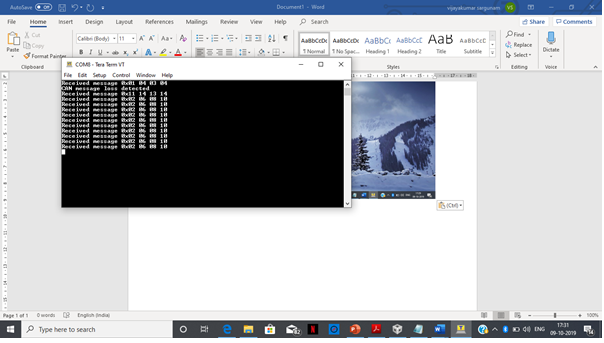
Output:

Receiver Code:
/*
 * CAN bus LED controller slave firmware
 * Written for TI Tiva TM4C123GH6PM
 */

#include <stdint.h>
#include <stdbool.h>

#include "inc/hw_memmap.h"
#include "inc/hw_types.h"
#include "inc/hw_can.h"
#include "inc/hw_ints.h"
#include "driverlib/can.h"
#include "driverlib/interrupt.h"
#include "driverlib/sysctl.h"
#include "driverlib/gpio.h"
#include "driverlib/uart.h"
#include "driverlib/pin_map.h"

#include "utils/uartstdio.h"


volatile bool rxFlag = 0; // msg recieved flag
volatile bool errFlag = 0; // error flag
unsigned int sysClock; // clockspeed in hz

// CAN interrupt handler
void CANIntHandler(void) {

   unsigned long status = CANIntStatus(CAN1_BASE, CAN_INT_STS_CAUSE); // read interrupt status

   if(status == CAN_INT_INTID_STATUS) { // controller status interrupt
      status = CANStatusGet(CAN1_BASE, CAN_STS_CONTROL);
      errFlag = 1;
   } else if(status == 1) { // msg object 1
      CANIntClear(CAN1_BASE, 1); // clear interrupt
      rxFlag = 1; // set rx flag
      errFlag = 0; // clear any error flags
   }
   else if(status == 2) { // msg object 1
         CANIntClear(CAN1_BASE, 2); // clear interrupt
         rxFlag = 1; // set rx flag
         errFlag = 0; // clear any error flags
   }
   else if(status == 3) { // msg object 1
         CANIntClear(CAN1_BASE, 3); // clear interrupt
         rxFlag = 1; // set rx flag
         errFlag = 0; // clear any error flags
   }else { // should never happen
      UARTprintf("Unexpected CAN bus interrupt\n");
   }
}

int main(void) {

   tCANMsgObject msg1,msg2,msg3;// the CAN msg object
   unsigned char msg1Data[8]; // 8 byte buffer for rx message data
   unsigned char msg2Data[8]; // 8 byte buffer for rx message data
   unsigned char msg3Data[8]; // 8 byte buffer for rx message data
   // Run from crystal at 50Mhz
    sysClock = SysCtlClockFreqSet((SYSCTL_XTAL_25MHZ | SYSCTL_OSC_MAIN | SYSCTL_USE_PLL | SYSCTL_CFG_VCO_480), 120000000);

   // Set up debugging UART
   SysCtlPeripheralEnable(SYSCTL_PERIPH_GPIOA);
   SysCtlPeripheralEnable(SYSCTL_PERIPH_UART0);
   GPIOPinConfigure(GPIO_PA0_U0RX);
   GPIOPinConfigure(GPIO_PA1_U0TX);
   GPIOPinTypeUART(GPIO_PORTA_BASE, GPIO_PIN_0 | GPIO_PIN_1);
   UARTStdioConfig(0, 115200, sysClock); // 115200 baud


   SysCtlPeripheralEnable(SYSCTL_PERIPH_GPIOB); // enable CAN1 GPIO peripheral
   GPIOPinConfigure(GPIO_PB0_CAN1RX);
   GPIOPinConfigure(GPIO_PB1_CAN1TX);
   GPIOPinTypeCAN(GPIO_PORTB_BASE, GPIO_PIN_0 | GPIO_PIN_1);
   SysCtlPeripheralEnable(SYSCTL_PERIPH_CAN1);
   CANInit(CAN1_BASE);
   CANBitRateSet(CAN1_BASE, sysClock, 500000);
   CANIntRegister(CAN1_BASE, CANIntHandler); // use dynamic vector table allocation
   CANIntEnable(CAN1_BASE, CAN_INT_MASTER | CAN_INT_ERROR | CAN_INT_STATUS);
   IntEnable(INT_CAN1);
   CANEnable(CAN1_BASE);
   //IntMasterEnable();
   // Set up LED driver
//   RGBInit(1);

   // Use ID and mask 0 to recieved messages with any CAN ID
   msg1.ui32MsgID = 1;
 //msg.ui32MsgIDMask = 0;
   msg1.ui32Flags = MSG_OBJ_RX_INT_ENABLE | MSG_OBJ_USE_ID_FILTER;
   msg1.ui32MsgLen = 8; // allow up to 8 bytes
   // Use ID and mask 0 to recieved messages with any CAN ID
    msg2.ui32MsgID = 2;
  //msg.ui32MsgIDMask = 0;
    msg2.ui32Flags = MSG_OBJ_RX_INT_ENABLE | MSG_OBJ_USE_ID_FILTER;
    msg2.ui32MsgLen = 8; // allow up to 8 bytes

    // Use ID and mask 0 to recieved messages with any CAN ID
     msg3.ui32MsgID = 3;
   //msg.ui32MsgIDMask = 0;
     msg3.ui32Flags = MSG_OBJ_RX_INT_ENABLE | MSG_OBJ_USE_ID_FILTER;
     msg3.ui32MsgLen = 8; // allow up to 8 bytes
   // Load msg into CAN peripheral message object 1 so it can trigger interrupts on any matched rx messages
   //CANMessageSet(CAN1_BASE, 1, &msg1, MSG_OBJ_TYPE_RX);
  CANMessageSet(CAN1_BASE, 2, &msg2, MSG_OBJ_TYPE_RX);
  //CANMessageSet(CAN1_BASE, 3, &msg3, MSG_OBJ_TYPE_RX);
 //  unsigned int colour[3];
//   float intensity;
   unsigned int rcv1msg[4];
   unsigned int rcv2msg[4];
   unsigned int rcv3msg[4];

   while(1) {
	  //IntMasterEnable();
      if(rxFlag) { // rx interrupt has occured

         msg2.pui8MsgData = msg2Data; // set pointer to rx buffer
         CANMessageGet(CAN1_BASE, 2, &msg2, 0); // read CAN message object 1 from CAN peripheral

         rxFlag = 0; // clear rx flag

         if(msg2.ui32Flags & MSG_OBJ_DATA_LOST)

          { // check msg flags for any lost messages

              UARTprintf("CAN message loss detected\n");


              msg2.ui32Flags &= ~MSG_OBJ_DATA_LOST;


           // Set the new state of the message object.

              CANMessageSet(CAN1_BASE, 2, &msg2, MSG_OBJ_TYPE_RX);

         }


     	                rcv2msg[0] = msg2Data[0] ;
     			rcv2msg[1] = msg2Data[1] ;
     			rcv2msg[2] = msg2Data[2] ;
     			rcv2msg[3] = msg2Data[3] ;

     			// write to UART for debugging
     			UARTprintf("Received message 0x%02X %02X %02X %02X\n", rcv2msg[0], rcv2msg[1],rcv2msg[2],rcv2msg[3]);


      }
     else
     {
#if DEBUG
    	 if(bMsgFlag == 0)
    	 {
    		 UARTPrintf("cant able to receive message");
    		 bMsgFlag = 1;
    	 }
#endif

     }
  }


}
Output: