This thread has been locked.

If you have a related question, please click the "Ask a related question" button in the top right corner. The newly created question will be automatically linked to this question.

TM4C1294KCPDT: drive LCD solution

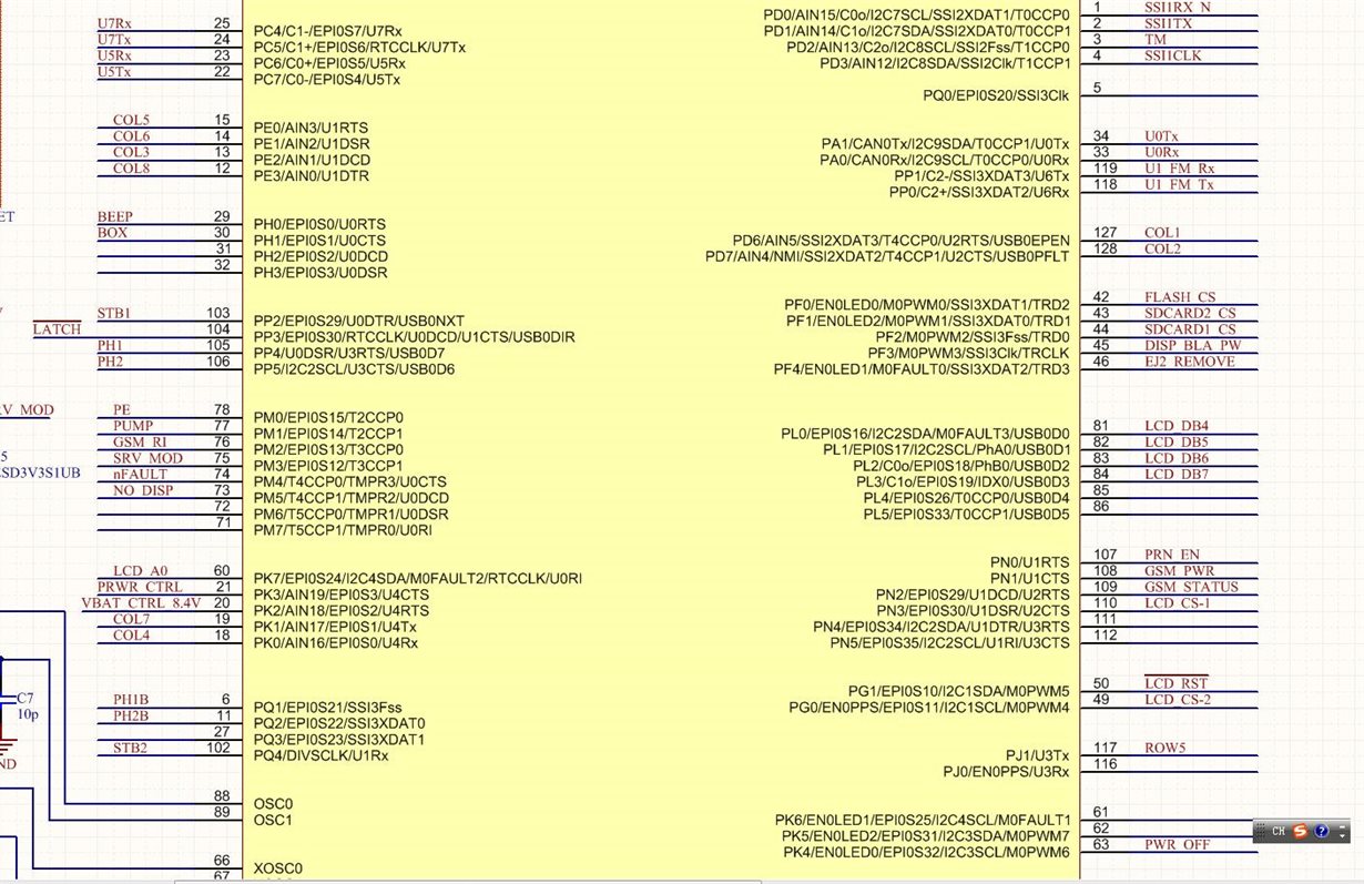
Part Number: TM4C1294KCPDT
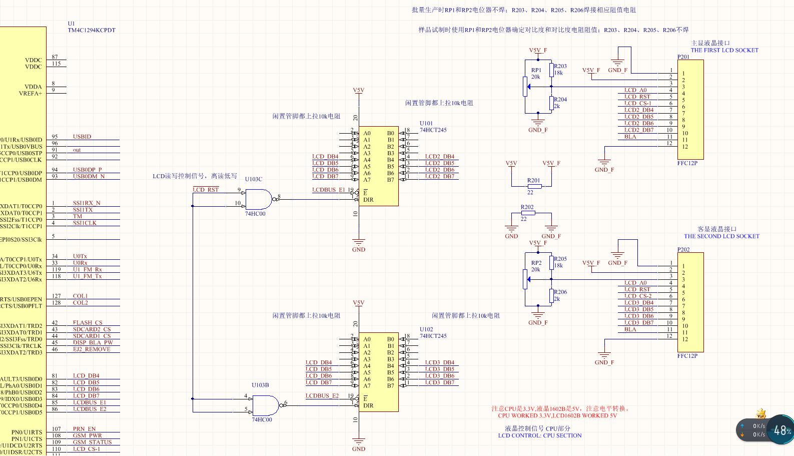
Other Parts Discussed in Thread: SN74HCT245, SN74LVC4245A, EK-TM4C1294XL

Hi

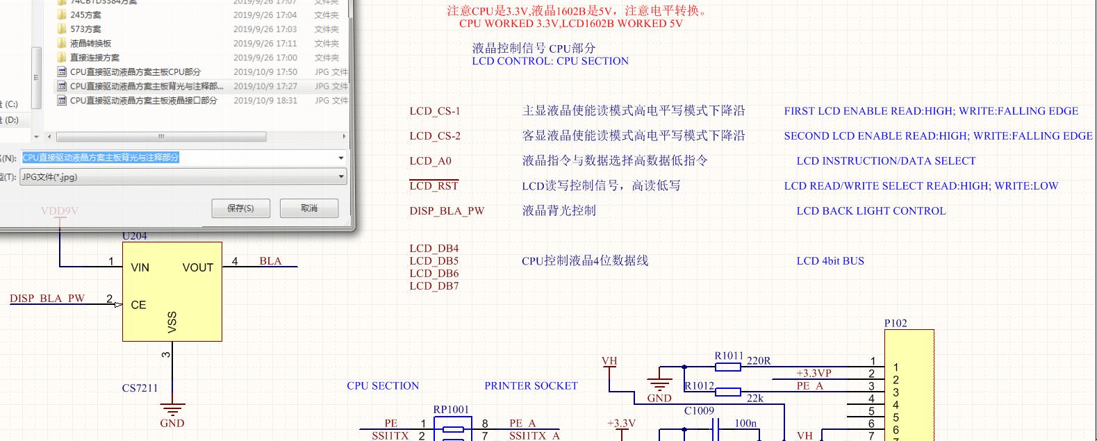
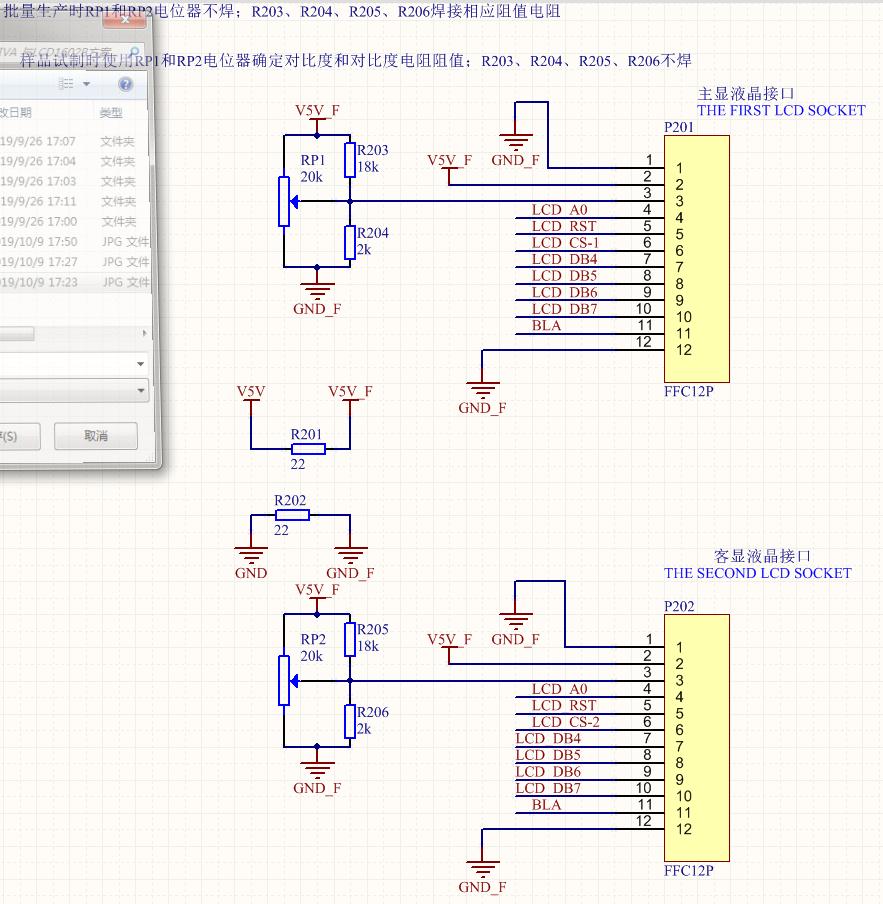
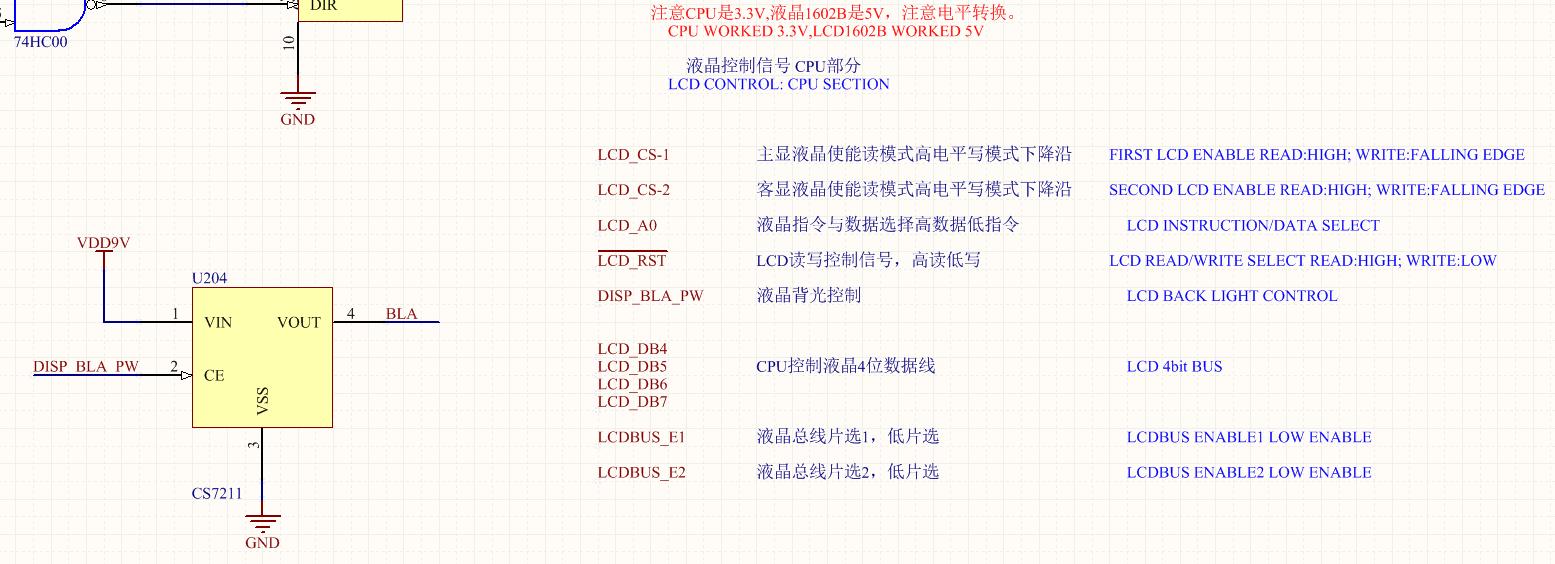
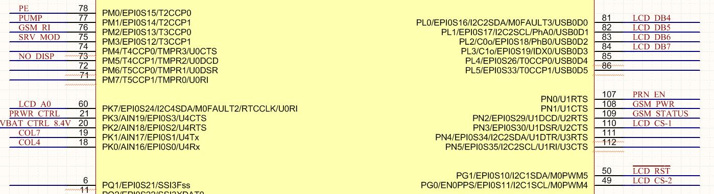
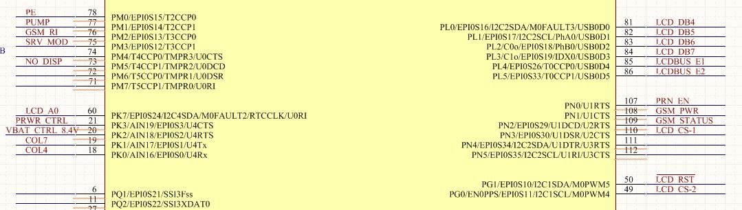
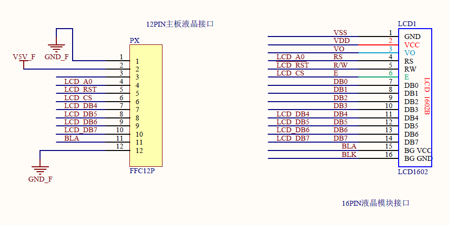
In the figure, the CPU uses TI's TM4C1294KCPDT with a 3.3V voltage. The external liquid crystal uses 5V voltage, and the CPU board and the LCD board are connected by a 30-50CM FFC cable;
Two programs are now designed:
The first solution: the CPU is directly connected to the LCD. This solution is the simplest, but I don't know if the CPU can withstand the logic level of 5V, and whether the signal output by the CPU can pass the 30-50cm cable to the LCD. Does the CPU have this driving capability? ? Moreover, this scheme may not be very good when reading the liquid crystal (although it can be written and not read during programming).
The second solution: the CPU connects the 4-bit bus to the LCD through the SN74HCT245. This solution can read the contents of two LCDs separately (but not simultaneously), and the driving capability is stronger than the first one, but some devices need to be added. The cost is higher, and the CPU needs to occupy two additional pins, and does the 3V3 clamp diode protection be required between the 3.3V CPU and the 5V-powered SN74HCT245?

Just change the LCD keyboard on the original product, the other parts are mature, I personally tend to connect directly but I am not sure about the processing of the interface, I hope you can give some advice.
Thanks 
Elsa Duan
  • Hello Elsa,

    The TM4C1294KCPDT is not 5V tolerant. I was trying to see from the datasheet for the LCD if it would output a 5V signal or if it would work a 3.3V logic, but I could not see conclusively. If you can figure that out, it would be helpful.

    If it works at 3.3V logic for the connections that need to go to the MCU then you can just tie it directly to the MCU. I've worked with similar displays in the past with 3V MCU's like MSP430 and my recollection is the LCD is powered at 5V but the I/O work at 3.3V. I don't have the part number for that display handy though so it may have been different and thus operated differently.

    Beyond the voltage issue, the MCU can definitely handle the communication to the device from a drive perspective. The MCU would just sends commands so basic GPIO drive current is plenty for that. The bulk of the current for the LCD is going to come from the 5V connection and the 3.3V backlight connection which should come from your power sources.

    If the outputs to the MCU are in fact at 5V, then you'd need something like a resistor divider to drive down the outputs to 3.3V logic level in order to prevent damaging the TM4C.

    The SN74HCT245 doesn't seem relevant here as it wouldn't handle stepping down the voltage.

  • Vendor's Ralph has nicely described the MCU's sensitivities.     

    Follows now the perspective from the 'Character LCD' side.

    • Many vendors (> 5) have labeled their 2x16 character modules as LCD1602B.     (thus - the spec of your (actual) Lcd  (should)  be linked here...)
    • 2x16 Lcd Modules may - or may not - accept 3V3 signal levels.   (even when - especially when - powered via 5V.)   
    • Original Lcd Control ICs [HD44780 & (even) earlier HD43160] indeed accepted 3V3 data levels when powered from 5V.    However - many newer 'clone' Lcd Controllers - when powered from 5V - will not accept 3V3 data & control signals!    Such explains why a datasheet IS required...
    • There is  'strange & disturbing use' of the label 'LCD RST' - to drive the Lcd's R/W pin.   MCU Reset is NOT to be applied here!   Solid & persistently controlled signals ARE required by the Lcd's R/W input - which the MCU's (assumed) Reset cannot possibly provide.
    • It is 'During the Read' of the Lcd that the Lcd Module's data pins (i.e. DB4-DB7 here) will output (near) 5V - which may prove harmful to your '129 family MCU.'
    • The Lcd's "E' pin is labeled as 'Lcd CS' - which it is not.   Signal 'E' is to be 'positively' pulsed w/each 4 bit data transfer - be it data or command - while a 'normal CS signal' lasts throughout the entire device's transaction.   (i.e. the 'E' signal is more active than 'CS.'    In the past the 'E' signal was pulsed high for 450nS (min) - newer controllers are able to accept 250nS (min) - but check your data sheet.)
    • The Lcd is being placed into the (more difficult & demanding) '4 bit mode.'    This saves 4 I/O - yet adds complexity - & makes the Lcd especially vulnerable to noise sources.    The Lcd relies upon the properly sequenced, 'Dual 4 bit data presentation' - while '8 bit mode' has 'No such Sequencing Demand.'    Unless one regularly 'reads' the Lcd - the fact that the screen has become 'disordered' (i.e. completely random & unreadable) may continue for long periods - undetected!    (4 bit mode is responsible for tens of thousands of 'lost hours' - saving 4 bits (may) be an unwise choice... it may (appear) to 'perform correctly when operated w/in one's pristine/development lab' - yet 'suffer repeated (unacceptable) 'disorder' - when exposed to the 'real-world!')

    With these findings - the insertion of a, 'Bus Transceiver & '3V3 - 5V' Voltage Translator IC' is well indicated.    My firm has enjoyed success w/Vendor's  "SN74LVC4245A" - which provides (both) transceiver & '3V3 to 5V' (and vice-versa) voltage translation.     Note that the insertion (past suggested) of a voltage divider (must) fail - as it will (even further) reduce the 3V3 output of the MCU - while attempting to write to the Lcd!

    Tags:  Character Lcd Module Use w/TM4C MCUs - Bus Transceiver w/'Bi-Di' Voltage Translator - requirement for posters to 'link' (real) data sheets

  • Dears

    Attached is a screenshot of the new schematic. In addition, LCD_12TO16.pdf and LCD module data have been sent before, here no longer re-sent.           

    The basic function is to use four pins of CPU (TM4C1294KCPDT) to realize a 4-bit bus, which controls two liquid crystals (1602B or similar products), in which CPU works at 3.3V; LCD works at 5V, and the main board and LCD board are connected by FFC or FPC cable of 30-50cm length. The problem lies in two aspects: one is how to make the CPU control two LCDs at the same time; the other is how to realize the conversion of 3.3V and 5V between the CPU and LCD. I have designed two schemes: one is that the CPU drives two LCDs directly, so that the circuit is simplest and the cost is lowest. In theory, it can write the same content to two LCDs at the same time. But the problem of this scheme is that it is not clear whether one LCD will be affected by another when the CPU reads one LCD information, and the other is whether the CPU working at 3.3V can properly drive the 5V LCD. The second case is that the CPU accesses two LCDs through two 74HCT 245 pieces. This scheme is more complex and adds many devices, and takes up two additional pins of the CPU, LCDBUS_E1 and LCDBUS_E2. In addition, is it necessary to add 3.3V embedded protection and isolation resistance between CPU and HCT 245? The advantage of this scheme is that the drive capability is higher than that of CPU direct drive, and it can theoretically control the reading and writing of two LCDs separately. I personally prefer CPU direct drive for these two schemes. In addition, LCD works in 5V version and 3.3V version, but 3.3V version is more expensive than 5V version. Therefore, the preferred 5V can also use 3V if it can not solve 3V 5V conversion problem, but the overall scheme is more concise and the cost can not be higher than that of using 5V version.   

    CPU Direct Drive LCD Scheme Main Board CPU:

    CPU Direct Drive LCD Scheme Main Board Backlight and Annotation:

    CPU Direct Drive LCD Scheme Main Board LCD Interface:

    HCT 245 driver CPU:

    HCT 245 Driving Scheme HCT 245 and LCD Interface:

    HCT 245 Driver Backlight and Annotation:

    LCD control pin summary:           

    LCD_A0 (PK7; 60 feet)           

    LCD_CS1 (PN3; 110 feet)           

    LCD_CS2 (PG0; 49 feet)           

    LCD_RST (PG1; 50 feet)           

    LCD_DB4~DB7 (PL0~PL3, 81~84 feet)           

    LCDBUS_E1 (PL4; 85 feet)           

    LCDBUS_E2 (PL5; 86 feet)           

    DISP_BLA_PW (PF3; 45 feet)

    Thanks

    Elsa Duan

  • Hello Elsa,

    The TM4C cannot tolerate 5V inputs onto the device pins. From your description you need to either use the 3V version or you need to have a voltage translator to step down the 5V signals to 3V for the TM4C. As you identified, that would incur added system cost.

  • Hello Elsa,

    Are you not concerned to run a ribbon cable 45'-110'? Recently discovered a much easier transport for long distance wires via UART TX/RX signals. The Nextion color LCD can be driven by 423 serial driver to extend the TM4C1294 UART signals to over 1000' or more on shielded twisted pairs of Teflon coated wire for industrial purpose. Nextion is receiving & transmitting @12-14k CPS without any framing errors (115200bps) via EK-TM4C1294XL on four 6" jumper wires connected to booster pack headers.

    Perhaps CB1 could advise on the distance part of your LCD choice if it is even doable without major issues.

  • One of 'multiple Dears' arrives for 'one last' (borderline ignored) Lcd briefing.

    user5707026 said:
    LCD module data have been sent before, here no longer re-sent.           

    That's not an especially friendly nor helpful response - is it?    Both staff & I have reread your initial post - find no (obvious) link to the Lcd's datasheet.    And again - 1602B is fairly generic - several vendors produce these.

    Initial post stated 30-50cm cable length - which (somehow) has now ballooned to 45-110 FEET!    That HUGE CHANGE warrants (some) description - does it not?

    Past bullet points listed in poster's behalf received 'No/Zero' comment - thus 'adding to the mix'  (here/now) likely registers as 'pointless.'

    In response (now) to BP101's query - it is doubtful (i.e.  Have NO CHANCE WHATSOEVER!)  that the MCU's (any MCU - btw)  unaided GPIO signals could successfully travel such distances!     (we have had multiple clients attempt such cable runs (5-7 meters - based upon cable quality - is the best (ever) achieved.)      Regularly spaced amplification stages are NECESSARY - yet a proper Serial Interface proves 'Orders of Magnitude' SUPERIOR!   

    Beyond that - the  'Open Invitation' to  'ESD' and strong 'Antenna Effect' - renders such (unshielded cable lengths) a, 'Not even to be considered' decision!    Such lengths place the MCU itself - as well as the Lcd - in serious jeopardy!

    BP101 suggests UART via serial driver - yet that would require a 2nd MCU to be installed at the Lcd(s) side - as well.   (to perform the required, 'serial to parallel' data conversion - needed by the Lcd)   

    The  (earlier)  30-50cm cable lengths  are 'borderline' doable - the 'spectacular extensions' - not so much!    This application 'cries out' for a 'proper Serial Connection employing line drivers' and a 2nd MCU (of some form) to be co-located w/the Lcd(s).

    Tag:  30-50cm shifts to 110 feet - link to datasheet 'withheld' -  (poster) unresponsive...

  • Hello CB1

    cb1_mobile said:
    BP101 suggests UART via serial driver - yet that would require a 2nd MCU to be installed at the Lcd(s) side - as well.   (to perform the required, 'serial to parallel' data conversion - needed by the Lcd) 

    MCU is built into the Nextion LCD, thus only have to provide 3v3 TTL to RS423 converter PCB in front  with +5vdc, +/-12vdc power supply. Time is spent on hardware rather than months even years on LCD graphics design. The main problem for me was the weak documentation of widgets data types and some counter intuitive protocol claims later found as misleading.

    Not all serial data is sent in ASCII, only the commands and text boxes are. So the number/Xfloat boxes, gauges, wave scopes data are sent in RAW integer data type. All is a bit confusing until custom Rx/Tx UART handler code is made functional. One can use UARTPrintf() to command and send data variables via uartstdio.c if not being used for other debug console etc. 

  • BP101 said:
    MCU is built into the Nextion LCD

    Mon Ami,

    This thread focuses upon a 'Plain Jane' standard 2x16 Character Lcd  (maybe 2 of them) - not your Nextion.   

    Your description of, 'Data & Commands' used by Nextion appear 'outside' the focus of this thread - and unlikely to prove useful.     (unless you can 'steer' poster to your Nextion..)

    Tag:  Nextion (somehow) enters the fray...

  • Ideally long distance calls require long distance solutions poster has not, did not consider are even  possible for typical LCD modules. For that reason I'm out, at least until the poster responds to have some interest in pursuing their posted issues.