Part Number: EK-TM4C1294XL
Other Parts Discussed in Thread: TM4C1294NCPDT
Tool/software: Code Composer Studio
Hello,
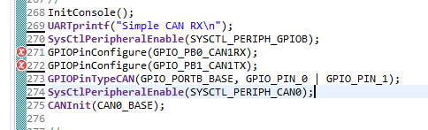
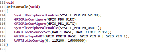
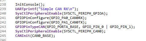
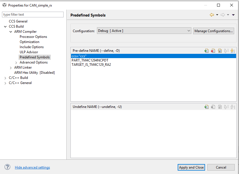
I want to read data from my encoder (CAN) and I'm using EK-TM4C1294XL & TJA1050. Also I'm using CAN_simple_RX but i can not read data.

//*****************************************************************************
//
// simple_rx.c - Example demonstrating simple CAN message reception.
//
// Copyright (c) 2010-2017 Texas Instruments Incorporated. All rights reserved.
// Software License Agreement
//
// Redistribution and use in source and binary forms, with or without
// modification, are permitted provided that the following conditions
// are met:
//
// Redistributions of source code must retain the above copyright
// notice, this list of conditions and the following disclaimer.
//
// Redistributions in binary form must reproduce the above copyright
// notice, this list of conditions and the following disclaimer in the
// documentation and/or other materials provided with the
// distribution.
//
// Neither the name of Texas Instruments Incorporated nor the names of
// its contributors may be used to endorse or promote products derived
// from this software without specific prior written permission.
//
// THIS SOFTWARE IS PROVIDED BY THE COPYRIGHT HOLDERS AND CONTRIBUTORS
// "AS IS" AND ANY EXPRESS OR IMPLIED WARRANTIES, INCLUDING, BUT NOT
// LIMITED TO, THE IMPLIED WARRANTIES OF MERCHANTABILITY AND FITNESS FOR
// A PARTICULAR PURPOSE ARE DISCLAIMED. IN NO EVENT SHALL THE COPYRIGHT
// OWNER OR CONTRIBUTORS BE LIABLE FOR ANY DIRECT, INDIRECT, INCIDENTAL,
// SPECIAL, EXEMPLARY, OR CONSEQUENTIAL DAMAGES (INCLUDING, BUT NOT
// LIMITED TO, PROCUREMENT OF SUBSTITUTE GOODS OR SERVICES; LOSS OF USE,
// DATA, OR PROFITS; OR BUSINESS INTERRUPTION) HOWEVER CAUSED AND ON ANY
// THEORY OF LIABILITY, WHETHER IN CONTRACT, STRICT LIABILITY, OR TORT
// (INCLUDING NEGLIGENCE OR OTHERWISE) ARISING IN ANY WAY OUT OF THE USE
// OF THIS SOFTWARE, EVEN IF ADVISED OF THE POSSIBILITY OF SUCH DAMAGE.
//
// This is part of revision 2.1.4.178 of the Tiva Firmware Development Package.
//
//*****************************************************************************
#include <stdbool.h>
#include <stdint.h>
#include "inc/hw_can.h"
#include "inc/hw_ints.h"
#include "inc/hw_memmap.h"
#include "inc/hw_types.h"
#include "driverlib/can.h"
#include "driverlib/gpio.h"
#include "driverlib/interrupt.h"
#include "driverlib/pin_map.h"
#include "driverlib/sysctl.h"
#include "driverlib/uart.h"
#include "utils/uartstdio.h"
//*****************************************************************************
//
//! \addtogroup can_examples_list
//! <h1>Simple CAN RX (simple_rx)</h1>
//!
//! This example shows the basic setup of CAN in order to receive messages
//! from the CAN bus. The CAN peripheral is configured to receive messages
//! with any CAN ID and then print the message contents to the console.
//!
//! This example uses the following peripherals and I/O signals. You must
//! review these and change as needed for your own board:
//! - CAN0 peripheral
//! - GPIO port B peripheral (for CAN0 pins)
//! - CAN0RX - PB4
//! - CAN0TX - PB5
//!
//! The following UART signals are configured only for displaying console
//! messages for this example. These are not required for operation of CAN.
//! - GPIO port A peripheral (for UART0 pins)
//! - UART0RX - PA0
//! - UART0TX - PA1
//!
//! This example uses the following interrupt handlers. To use this example
//! in your own application you must add these interrupt handlers to your
//! vector table.
//! - INT_CAN0 - CANIntHandler
//
//*****************************************************************************
//*****************************************************************************
//
// A counter that keeps track of the number of times the RX interrupt has
// occurred, which should match the number of messages that were received.
//
//*****************************************************************************
volatile uint32_t g_ui32MsgCount = 0;
//*****************************************************************************
//
// A flag for the interrupt handler to indicate that a message was received.
//
//*****************************************************************************
volatile bool g_bRXFlag = 0;
//*****************************************************************************
//
// A flag to indicate that some reception error occurred.
//
//*****************************************************************************
volatile bool g_bErrFlag = 0;
//*****************************************************************************
//
// This function sets up UART0 to be used for a console to display information
// as the example is running.
//
//*****************************************************************************
void
InitConsole(void)
{
//
// Enable GPIO port A which is used for UART0 pins.
// TODO: change this to whichever GPIO port you are using.
//
SysCtlPeripheralEnable(SYSCTL_PERIPH_GPIOA);
//
// Configure the pin muxing for UART0 functions on port A0 and A1.
// This step is not necessary if your part does not support pin muxing.
// TODO: change this to select the port/pin you are using.
//
GPIOPinConfigure(GPIO_PA0_U0RX);
GPIOPinConfigure(GPIO_PA1_U0TX);
//
// Enable UART0 so that we can configure the clock.
//
SysCtlPeripheralEnable(SYSCTL_PERIPH_UART0);
//
// Use the internal 16MHz oscillator as the UART clock source.
//
UARTClockSourceSet(UART0_BASE, UART_CLOCK_PIOSC);
//
// Select the alternate (UART) function for these pins.
// TODO: change this to select the port/pin you are using.
//
GPIOPinTypeUART(GPIO_PORTA_BASE, GPIO_PIN_0 | GPIO_PIN_1);
//
// Initialize the UART for console I/O.
//
UARTStdioConfig(0, 115200, 16000000);
}
//*****************************************************************************
//
// This function is the interrupt handler for the CAN peripheral. It checks
// for the cause of the interrupt, and maintains a count of all messages that
// have been received.
//
//*****************************************************************************
void
CANIntHandler(void)
{
uint32_t ui32Status;
//
// Read the CAN interrupt status to find the cause of the interrupt
//
ui32Status = CANIntStatus(CAN0_BASE, CAN_INT_STS_CAUSE);
//
// If the cause is a controller status interrupt, then get the status
//
if(ui32Status == CAN_INT_INTID_STATUS)
{
//
// Read the controller status. This will return a field of status
// error bits that can indicate various errors. Error processing
// is not done in this example for simplicity. Refer to the
// API documentation for details about the error status bits.
// The act of reading this status will clear the interrupt.
//
ui32Status = CANStatusGet(CAN0_BASE, CAN_STS_CONTROL);
//
// Set a flag to indicate some errors may have occurred.
//
g_bErrFlag = 1;
}
//
// Check if the cause is message object 1, which what we are using for
// receiving messages.
//
else if(ui32Status == 1)
{
//
// Getting to this point means that the RX interrupt occurred on
// message object 1, and the message reception is complete. Clear the
// message object interrupt.
//
CANIntClear(CAN0_BASE, 1);
//
// Increment a counter to keep track of how many messages have been
// received. In a real application this could be used to set flags to
// indicate when a message is received.
//
g_ui32MsgCount++;
//
// Set flag to indicate received message is pending.
//
g_bRXFlag = 1;
//
// Since a message was received, clear any error flags.
//
g_bErrFlag = 0;
}
//
// Otherwise, something unexpected caused the interrupt. This should
// never happen.
//
else
{
//
// Spurious interrupt handling can go here.
//
}
}
//*****************************************************************************
//
// Configure the CAN and enter a loop to receive CAN messages.
//
//*****************************************************************************
int
main(void)
{
#if defined(TARGET_IS_TM4C129_RA0) || \
defined(TARGET_IS_TM4C129_RA1) || \
defined(TARGET_IS_TM4C129_RA2)
uint32_t ui32SysClock;
#endif
tCANMsgObject sCANMessage;
uint8_t pui8MsgData[8];
//
// Set the clocking to run directly from the external crystal/oscillator.
// TODO: The SYSCTL_XTAL_ value must be changed to match the value of the
// crystal used on your board.
//
#if defined(TARGET_IS_TM4C129_RA0) || \
defined(TARGET_IS_TM4C129_RA1) || \
defined(TARGET_IS_TM4C129_RA2)
ui32SysClock = SysCtlClockFreqSet((SYSCTL_XTAL_25MHZ |
SYSCTL_OSC_MAIN |
SYSCTL_USE_OSC)
25000000);
#else
SysCtlClockSet(SYSCTL_SYSDIV_1 | SYSCTL_USE_OSC | SYSCTL_OSC_MAIN |
SYSCTL_XTAL_16MHZ);
#endif
//
// Set up the serial console to use for displaying messages. This is
// just for this example program and is not needed for CAN operation.
//
InitConsole();
UARTprintf("Simple CAN RX\n");
//
// For this example CAN0 is used with RX and TX pins on port B4 and B5.
// The actual port and pins used may be different on your part, consult
// the data sheet for more information.
// GPIO port B needs to be enabled so these pins can be used.
// TODO: change this to whichever GPIO port you are using
//
SysCtlPeripheralEnable(SYSCTL_PERIPH_GPIOB);
//
// Configure the GPIO pin muxing to select CAN0 functions for these pins.
// This step selects which alternate function is available for these pins.
// This is necessary if your part supports GPIO pin function muxing.
// Consult the data sheet to see which functions are allocated per pin.
// TODO: change this to select the port/pin you are using
//
GPIOPinConfigure(GPIO_PB4_CAN0RX);
GPIOPinConfigure(GPIO_PB5_CAN0TX);
//
// Enable the alternate function on the GPIO pins. The above step selects
// which alternate function is available. This step actually enables the
// alternate function instead of GPIO for these pins.
// TODO: change this to match the port/pin you are using
//
GPIOPinTypeCAN(GPIO_PORTB_BASE, GPIO_PIN_4 | GPIO_PIN_5);
//
// The GPIO port and pins have been set up for CAN. The CAN peripheral
// must be enabled.
//
SysCtlPeripheralEnable(SYSCTL_PERIPH_CAN0);
//
// Initialize the CAN controller
//
CANInit(CAN0_BASE);
//
// Set up the bit rate for the CAN bus. This function sets up the CAN
// bus timing for a nominal configuration. You can achieve more control
// over the CAN bus timing by using the function CANBitTimingSet() instead
// of this one, if needed.
// In this example, the CAN bus is set to 500 kHz. In the function below,
// the call to SysCtlClockGet() or ui32SysClock is used to determine the
// clock rate that is used for clocking the CAN peripheral. This can be
// replaced with a fixed value if you know the value of the system clock,
// saving the extra function call. For some parts, the CAN peripheral is
// clocked by a fixed 8 MHz regardless of the system clock in which case
// the call to SysCtlClockGet() or ui32SysClock should be replaced with
// 8000000. Consult the data sheet for more information about CAN
// peripheral clocking.
//
#if defined(TARGET_IS_TM4C129_RA0) || \
defined(TARGET_IS_TM4C129_RA1) || \
defined(TARGET_IS_TM4C129_RA2)
CANBitRateSet(CAN0_BASE, ui32SysClock, 250000);
#else
CANBitRateSet(CAN0_BASE, SysCtlClockGet(), 250000);
#endif
//
// Enable interrupts on the CAN peripheral. This example uses static
// allocation of interrupt handlers which means the name of the handler
// is in the vector table of startup code. If you want to use dynamic
// allocation of the vector table, then you must also call CANIntRegister()
// here.
//
// CANIntRegister(CAN0_BASE, CANIntHandler); // if using dynamic vectors
//
CANIntEnable(CAN0_BASE, CAN_INT_MASTER | CAN_INT_ERROR | CAN_INT_STATUS);
//
// Enable the CAN interrupt on the processor (NVIC).
//
IntEnable(INT_CAN0);
//
// Enable the CAN for operation.
//
CANEnable(CAN0_BASE);
//
// Initialize a message object to be used for receiving CAN messages with
// any CAN ID. In order to receive any CAN ID, the ID and mask must both
// be set to 0, and the ID filter enabled.
//
sCANMessage.ui32MsgID = 0;
sCANMessage.ui32MsgIDMask = 0;
sCANMessage.ui32Flags = MSG_OBJ_RX_INT_ENABLE | MSG_OBJ_USE_ID_FILTER;
sCANMessage.ui32MsgLen = 8;
//
// Now load the message object into the CAN peripheral. Once loaded the
// CAN will receive any message on the bus, and an interrupt will occur.
// Use message object 1 for receiving messages (this is not the same as
// the CAN ID which can be any value in this example).
//
CANMessageSet(CAN0_BASE, 1, &sCANMessage, MSG_OBJ_TYPE_RX);
//
// Enter loop to process received messages. This loop just checks a flag
// that is set by the interrupt handler, and if set it reads out the
// message and displays the contents. This is not a robust method for
// processing incoming CAN data and can only handle one messages at a time.
// If many messages are being received close together, then some messages
// may be dropped. In a real application, some other method should be used
// for queuing received messages in a way to ensure they are not lost. You
// can also make use of CAN FIFO mode which will allow messages to be
// buffered before they are processed.
//
for(;;)
{
unsigned int uIdx;
//
// If the flag is set, that means that the RX interrupt occurred and
// there is a message ready to be read from the CAN
//
if(g_bRXFlag)
{
//
// Reuse the same message object that was used earlier to configure
// the CAN for receiving messages. A buffer for storing the
// received data must also be provided, so set the buffer pointer
// within the message object.
//
sCANMessage.pui8MsgData = pui8MsgData;
//
// Read the message from the CAN. Message object number 1 is used
// (which is not the same thing as CAN ID). The interrupt clearing
// flag is not set because this interrupt was already cleared in
// the interrupt handler.
//
CANMessageGet(CAN0_BASE, 1, &sCANMessage, 0);
//
// Clear the pending message flag so that the interrupt handler can
// set it again when the next message arrives.
//
g_bRXFlag = 0;
//
// Check to see if there is an indication that some messages were
// lost.
//
if(sCANMessage.ui32Flags & MSG_OBJ_DATA_LOST)
{
UARTprintf("CAN message loss detected\n");
}
//
// Print out the contents of the message that was received.
//
UARTprintf("Msg ID=0x%08X len=%u data=0x",
sCANMessage.ui32MsgID, sCANMessage.ui32MsgLen);
for(uIdx = 0; uIdx < sCANMessage.ui32MsgLen; uIdx++)
{
UARTprintf("%02X ", pui8MsgData[uIdx]);
}
UARTprintf("total count=%u\n", g_ui32MsgCount);
}
}
//
// Return no errors
//
return(0);
}
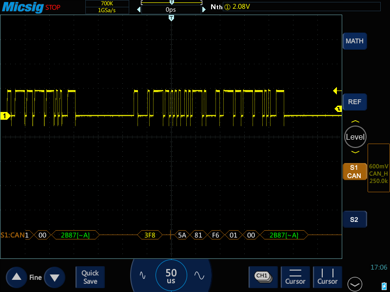


Encoder BaudRate = 250K
The data from the oscilloscope is correct. CAN communation and erncoder is running but i can not see any RX data on my Terminal screen.
Should i change the card or example ?
Thank you.