This thread has been locked.

If you have a related question, please click the "Ask a related question" button in the top right corner. The newly created question will be automatically linked to this question.

EK-TM4C1294XL: USB/PWM clock rate VCO 240MHz

Guru 55913 points
Part Number: EK-TM4C1294XL
Other Parts Discussed in Thread: TM4C1294KCPDT

Oddly after replacing  Tivaware v21171 SysCtlClockFreqSet() with v214178 SysCtlClockFreqSet() the SysCtlVcoGet() shows 240Mhz.

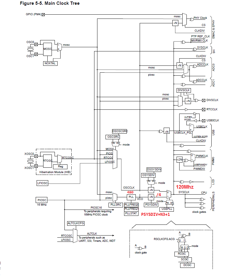
The worst part is USB PLL was set 480MHz, PLL divisor 16 and USB stopped enumerating. Adding the same clock change to TM4C1294KCPDT on custom PCB the USB/PWM peripherals kept working with the same PLL divisors being untouched.

Needless to say Tivaware v214178 changes to SysCtlClockFreqSet() has greatly confused me. Now the TM4C1294NCPDTi3 USB peripheral requires "PLL=240", "Divisor=4" or it will not even enumerate. So we have to wonder is the PWM clock divisor still correct if the VCO is indeed 240MHz versus 480MHz.  

Why does SysCtlVcoGet() now show the VCO=240MHz and how to make VCO=480Mhz as it was with v214178? Is 240Mhz more correct VCO speed and we were OverClocking the MCU???????????

Noticed this behavior in the past so reverted back to Tivaware v21171 SysCtlClockFreqSet() due to PWM clock divisor= PWM_SYS_CLK_DIV_2 rather than PWM_SYS_CLK_DIV_4 being VCO=480MHZ.

So all the past Tivaware driverlib peripheral documentation was presenting a false narrative the VCO=480MHz?

  • Hello BP101,

    The issue with the VCO is linked to Errata items SYSCTL#22 and SYSCTL#23, so yes the name is misleading right now.

    We've already identified this issue as a flaw within TivaWare that needs to be fixed, and have taken steps to adjust the naming conventions used in the next TivaWare release.

    The VCO is set to 240 MHz, but using a divide by 4 from it will provide the 60 MHz needed for USB. This is all setup in the APIs for TivaWare 2.1.4.178.

    I would suggest reading those two errata to understand more of the background as to why the changes were made to ensure long term system stability.

  • Ralph Jacobi said:
    The VCO is set to 240 MHz, but using a divide by 4 from it will provide the 60 MHz needed for USB. This is all setup in the APIs for TivaWare 2.1.4.178.

    Again why does the 480 PLL produce 240 MHz VCO and blow up USB and PWM peripherals as it now does? The TM4C1294KCPDT has the same 240MHz being set after several compiles via CCS7.

    So does this MOSC change require us to also change the USB and PWM previous divisors as it seem to now require? That is the point of the post as this change can be highly destructive to PWM inverter if the System Clock frequency divisor is not set correctly. 

    Is there a new VCO define we have to replace in the configuration below to achieve 480MHz VCO as previously being set?

     /* MPU uses MOSC driven PLL 480mHz/4 produce 120 MHz SYSCLK:
    	    Y1 = 25mHz XTAL HIGHFREQ. */
        	g_ui32SysClock =
        		MAP_SysCtlClockFreqSet((SYSCTL_XTAL_25MHZ |
    	                                SYSCTL_OSC_MAIN | SYSCTL_USE_PLL |
    	                                SYSCTL_CFG_VCO_480), 120000000);

  • Hello BP101,

    The errata item SYSCTL#22 ultimately only affect a small subset of devices, so in most situations you would appear to be able to use 480 MHz without issue. However, doing so would leave your system at risk for the errata item occurring and due to the nature of it, we cannot recommend anything other than using 240 MHz for the VCO. The USB is not impacted by the difference from 480 vs 240 MHz, though in theory if you wanted to use USB at 320 MHz it would because 320 MHz is not possible so it would be 160 MHz and that cannot be divided down to 60 MHz. I have not heard of PWM being impacted by this.

    The ADC module for highest frequency settings is a bit affected and needs special configuration to maximize the speed (a topic Bob has covered in prior posts).

    I will show you the code we are updating with the next TivaWare so you have some clarity.

    // Due to TM4C129x Errata Item SYSCTL#22, the SYSCTL_CFG_VCO_xxx configurations
    // have misleading *names* as currently defined as the VCO does not run at the
    // stated frequencies. To amend this, new *name* defintions are being used,
    // however the register configuration remains the same.
    // The old definitions will remain for compatibility with code ported from
    // older versions of TivaWare.
    #define SYSCTL_CFG_VCO_480      0xF1000000  // VCO is 480 MHz - Legacy
                                                // Does not work @ 480, use
                                                // SYSCTL_CFG_VCO_240 instead
    #define SYSCTL_CFG_VCO_320      0xF0000000  // VCO is 320 MHz - Legacy
                                                // Does not work @ 320, use
                                                // SYSCTL_CFG_VCO_160 instead
    #define SYSCTL_CFG_VCO_240      0xF1000000  // VCO is 240 MHz
    #define SYSCTL_CFG_VCO_160      0xF0000000  // VCO is 160 MHz

  • Hard to believe CPU Clock is still 120MHz rather than degraded to 60MHz. Yet SysCtlClockFreqSet() still returns 120MHz being questionable when VCO is 240MHz unless the CPU was being over clocked 240Mhz. The speed trade off has ramifications we must be made aware of. 

    Logic tells us CPU clock can't be the same frequency if VCO changes as revealed in system clock tree diagram.

  • Hello BP101,

    The SysCtlClockFreqSet function was updated so even with the lower VCO, the system clock still runs at 120 MHz. That has not changed, which is why as mentioned, only the ADC module at highest frequency sampling even needs any adjustment in how it is handled.

  • Ralph Jacobi said:
    The USB is not impacted by the difference from 480 vs 240 MHz, though in theory if you wanted to use USB at 320 MHz it would because 320 MHz is not possible so it would be 160 MHz and that cannot be divided down to 60 MHz. I have not heard of PWM being impacted by this.

    Seemingly the CPU PWM USB are all effected by 240MHz system  VCO clock. Have confirmed USB simply will not enumerate after changing the VCO divisors for 240 MHz in two MCU that were working correctly at 480MHz.

  • Hello BP101,

    I don't know where you are getting API's mixed up but USB works perfectly fine with the TivaWare 2.1.4.178 with the VCO running at 240 MHz (while falsely advertised by the define name to imply it is at 480 MHz).

    Load any TivaWare example unmodified into a LaunchPad and see for yourself.

  • Ralph Jacobi said:
    The SysCtlClockFreqSet function was updated so even with the lower VCO, the system clock still runs at 120 MHz.

    How is that even possible according to figure 5, the CPU USB and all Peripherals will then have 60MHz clock rate? The USB will not enumerate via usb_dev_bulk.c PLL=480 divisor 8 as it was previously defined for. Not everyone is going to update every part of Tivaware at the same time so this change is highly erratic that it can cause more problems than it resolves. 

  • Ok I see from clock tree if PSYSDIV=2 the PWM divisor remains the same, only the USB divisors have to be changed for 240MHz VCO. 

    So I'm terribly wrong about the CPU clock 60MHz if PSYSDIV=2 it remains 120MHz - that is what I was not seeing when USB stopped enumerating.

    I will check PSYSDIV value in CCS debug to confirm it indeed changed from 4 to 2.

  • See above edit: Tivaware v21171 PSYSDIV=4 and v214178 PSYSDIV=2 if CPU=120MHz and PWM Clock / 2 = 60MHz. Seemingly the v214178 manifest should indicate the PSYSDIV value was changed to 2 versus 4. Oddly no change to manifest was recorded.

  • Ralph Jacobi said:
    The SysCtlClockFreqSet function was updated so even with the lower VCO, the system clock still runs at 120 MHz.

    Actually V214178 did change the main clock tree PSYSDIV setting from N+3=4 to N+1=2. PSYSDIV value changed to 2 CPU=120Mhz and only USB/ADC divisors must be changed, PWM clock divisor remains unchanged.

  • Hi Ralph,

    Sorry to report I had to put PSYSDIV back to N3+1 as the ADC was slightly out of synchronization with the PWM module. Note worthy in all this forum discussion was SysCtlClockFreqSet() v21171 was not waiting for MOSC PUP interrupt as I reported in another post, there was no such delay. That alone was likely the cause perhaps why PLL failed to lock and PSYSDIV defaulted to POR setting of N1+1.  Do like the idea to test PLL lock bit not once but twice instead of in a count down sequence. The return(0) was very nice well thought out add on but forcing PSYSDIV=2 not so much in this case. 

    Another thing is the ADC divisor is being subtracted by -1 Tivaware ADCClockConfigSet()  and 7 passed in divisor becomes 6, produced 34.28MHz sample clock. Oddly it was working fair VCO=240MHz ADC divisor 15 prodcued 16Mhz sample clock, ideally desire 2MSPS rate.   

  • Hello BP101,

    Right, the PWM clock divisor being unchanged is why it is unaffected now I remember that too.

    Regarding the ADC, have a look at this post on how to get the full 2MSPS speed: https://e2e.ti.com/support/microcontrollers/other/f/908/p/690227/2545036#2545036

  • Look again, the 320VCO/5n-1 (hidden subtraction) does not make 32Mhz ADC clock, rather 5 alone (64Mhz) then n-1 = 80Mhz. Check the ADCCC register as I did via CCS debug. You will see the value entered as divisor is not what gets stored in the register. If we do the math on the register divisor value the sample frequency is much higher than expected.

  • Hello BP101,

    Again this is why we are updating the #define's for 2.2.0... the variable says 320VCO but it is actually running at 160MHz. So divide that by five would then result in 32 MHz.

    Furthermore, the TivaWare API is designed to simplify the input. You give the ADCClockConfigSet the number for the divider you want. So if you want to divide by 5, that is what you input in ADCClockConfigSet as Bob showed. The reason you see n-1 is because the device divides by a value 1 higher than input. So if you wrote 5 into the register, it would be divide by 6. You can see this on Page 1160 of the datasheet. Therefore, to ensure that it divides by 5, we need to subtract 1 from the input value of ADCClockConfigSet before the register write. So when inputting 5 into the ui32ClockDiv value for ADCClockConfigSet, the ADCCC register gets set to a value of 0x04 which maps to divide by 5 for the ADC.

  • Hi Ralph,

    So REG 66 shows /N+1 page 1158 very confusing as to what is the final value if Tivaware subtracts N-1 prior to REG 66 N+1 and CCS debug is less than we input.

    Ralph Jacobi said:
    Therefore, to ensure that it divides by 5, we need to subtract 1 from the input value of ADCClockConfigSet before the register write

    But I see your point to make the input divisor N+1 as Tivaware subtracts N-1 when REG66 adds it back in CLKDIV / N+1.