This thread has been locked.

If you have a related question, please click the "Ask a related question" button in the top right corner. The newly created question will be automatically linked to this question.

EK-TM4C1294XL: SPI communication

Part Number: EK-TM4C1294XL

Dear Sirs

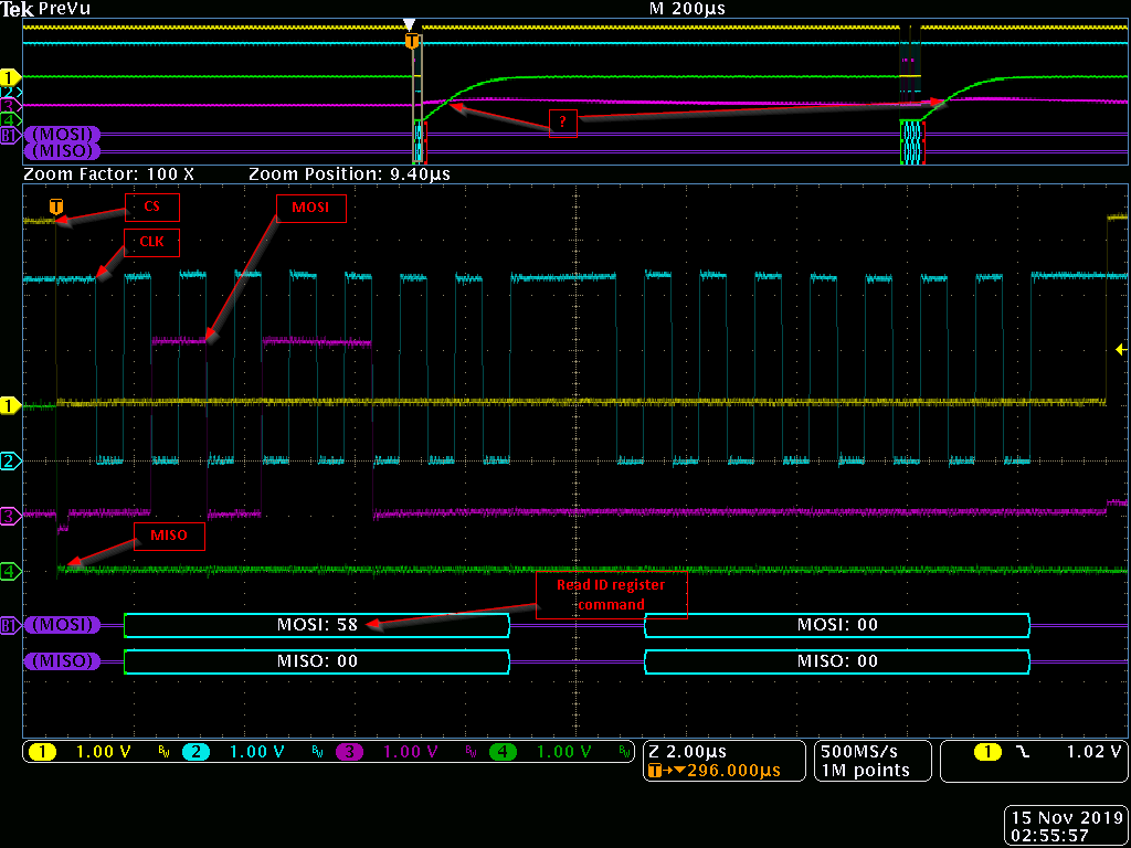
I'm using the EK-TM4C1294XL LaunchPad to talk to a ADI ADT7311 temperature sensor by way of the SPI bus.  I have CS, CLK and MOSI signals, but no MISO signa.  I've tried SSI0 through SSI2 with the same results.  Please see attached scope screen print.  Any help will be appreciated.  Please note the MISO signal rise.  I'm sure this is not right. 

  • Dennis McGlumphy said:

    Please note the MISO signal rise.  I'm sure this is not right.

    Greetings,

    Duly noted - and agreed - and 'outsider team/I Feel your Pain.'

    From your scope cap (we may have that same Tek Scope - btw) It is suspected that:

    • your chosen 'MISO' pin was incorrect or otherwise improper  (i.e. not fully/properly configured)
    • or there may be an 'issue' w/the ADC device and/or its configuration    (my group happens to consult for ADI)
    • there does appear to be an, 'Unholy linkage' between the SPI 'CS & MISO!'     Close review reveals that 'MISO' (Dives near ground - exactly as 'CS' makes that 'same transition!'    My team does not believe that represents, 'Normal/Customary SPI signal behavior!'
    • in light of the above - do INSURE that the ADI device is properly powered (especially when active) and that the ground attachment between your ADI (board, hopefully) and your MCU is robust...  (and present)

    What to do?    We suggest (temporarily):

    • Breaking the connection (only!) between your MCU's 'MISO' pin and ADI's device.   All other pins remain inter-connected!
    • then attaching your scope probe to the ADI's 'Slave Output Line' (same one which originally attached to MCU's MISO pin - now 'going nowhere')
    • and then, 'Noting How & If' the ADI device's output waveform changes  -  this will assist our determination of 'which' device is (most likely) faulting.

    As always - 'Full & Proper Data' ... 'Speeds, Eases & Enhances' our (and others') Remote Diagnostic Capabilities.    Vendor will surely, (and properly) Request your code - so that 'obvious code errors' may be 'Recognized & Corrected.'

    Your scope capture IS Helpful - yet by itself - proves less than 'fully aiding/enabling & conclusive...'

  • I am not concerned about the slow rise time on MISO (Master in Slave out) after CS (chip select) goes high. While I am no expert on the Analog Devices ADC, it does say in their datasheet that when CS is high the device is disabled. It does not surprise me that the DOUT pin of the ADT7311 would go high impedance when CS is high.

    I don't see anything wrong with the SPI signals coming from the TM4C. I agree with CB1 that you should double check the hardware interface with the ADT7311. The only other suggestion is that you might try the serial interface reset procedure described on page 19 of the ADT7311 datasheet.

    You can do this by sending four bytes of 0xFF out the SPI. Remember to then wait at least 500uS before sending the 0x58 command to read the ID register.

  • Dear Mr. Crosby

    I'm sorry for the late response.  I just wanted to make sure that all was working correctly.  I took your advice and added the software reset to my startup routine.  I've learned my lesson, never rely on power up default conditions.  Thank you for your help.  You can close this service request. 

  • While that rather unique, 'Serial Interface Reset' appears to work for now - it (may) prove wise to question its 'inclusion.'   

    My firm has recently concluded a reasonably intense (client paid) analysis of, 'Failed SPI Transactions' - over 35 different SPI devices were examined & tested - (few) provided such, 'unique Serial Interface Reset.'    Might this finding suggest that poster's chosen device - borders upon the 'sensitive?'    It is thus (highly) suggested that poster perform, 'Extensive, Post Power UP Testing - to insure that the device 'continues to perform to specification.'   (Note: a similar set of tests were performed upon I2C devices - highlights of that testing were reported (via client permission) here...)

    Another issue lurks - it has just been suggested to, 'Never rely upon 'Power Up' default conditions!'     Yet - there are MANY Peripheral Modules w/in the MCU - and it is 'Doubted that 'each/every one' - receives such 'Uniquely Dedicated Reset Treatment' - post power up & prior to first use!    

    Checking the 'Power Up' waveform appears wise - the 'balky Slave device may have 'detected, then signaled Difficulty!'    (i.e. inefficient board layout, excessive trace length and/or unwanted noise pick-up.)

    Might 'Bob' or another 'vendor agent' advise & inform - as to the 'best practice' in regards to, 'Software Commanded Reset  (beyond Power-Up Reset alone) of all MCU Peripheral Modules - prior to their use - immediately after Power Up?'   It IS noted that (almost) every single MCU Register clearly lists, 'Register Value upon Reset!'    Yet - unexplained - was the 'source of such reset.'    (believed to be Power-Up Reset...)

  • cb1_mobile

    I understand and agree with what you say.  In something that will be in production, I perform a complete power up analysis and design accordingly.  This project however, is being used for lab testing and I thought I could shortcut it.  Obviously, I was wrong.  Other peripheral in this project are under hardware reset control and therefore stable.  I understand that startup stability is the foundation for all embedded systems.  Thank you for the advise. 

  • Thank you - your quick yet detailed response is appreciated.

    Our intent is to 'alert you' - to what (may) be a 'sensitivity' issue - much confined to your chosen device.

    You might consider the following:

    • Generate multiple, 'Power-Up' repetitions - carefully note the (usual) behavior of your SPI device.
    • If and where possible - employ the same power supply as planned for your 'production design.'
    • Our findings revealed that 'most all' of the 35+ SPI devices we tested behaved properly (i.e. predictably) upon Power Up.
    • A 'few' devices had or developed 'issues' upon Power Up.   Even after a Re-Powering - these devices were the ones 'most likely' to 'suffer issues' while SPI transactions were underway.   (i.e. they 'somehow' became disordered after 50 to 250 successful SPI transactions - it is this linkage between, Power Up Sensitivity & later 'disorder' - which, 'rang our bell' - reading of your situation.)
    • Excessive pcb trace length, bends and/or 'other inductance adding elements' heightened the odds of these 'sensitive devices' suffering (disorder).
    • We deployed 3 different ARM Cortex MCUs (2 M4s, 1 M7) - in No case was the MCU found to be a 'contributor' to the Slave's disorder.
    • It appears 'useful' for you to repeat such testing across multiple of these Slave Devices - there is always the chance that you are encountering a (one-off) damaged or misbehaving device.

    Best of luck - and btw - has that past, 'slow rise MISO signal 'sharpened its response?'    (my group continues to see that earlier waveform as, 'failed/unwanted.')