This thread has been locked.

If you have a related question, please click the "Ask a related question" button in the top right corner. The newly created question will be automatically linked to this question.

TM4C123GH6PM: How to receive multi-word frame over SSI with one chip select pulse?

Part Number: TM4C123GH6PM

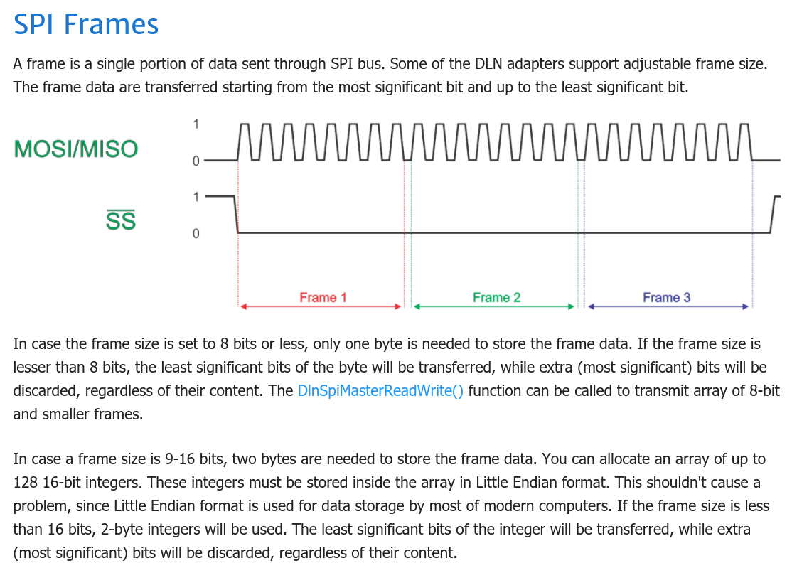
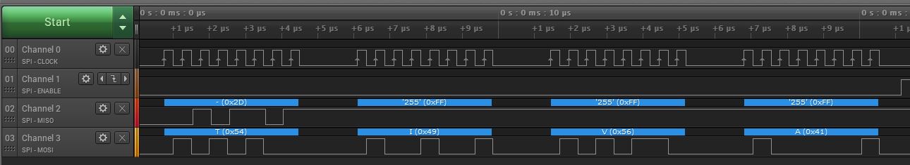
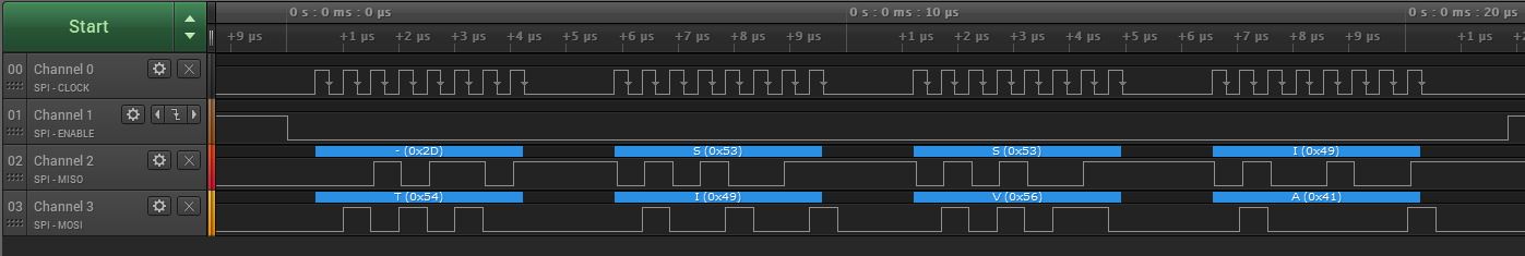
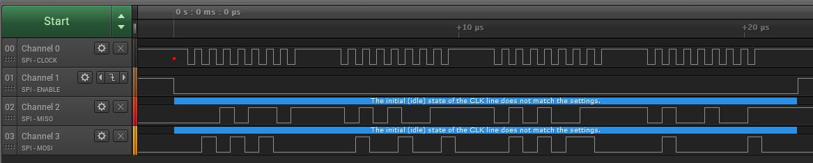
I use SSI interface as SPI slave port. If the master sends words with a chip select pulse for each serial word the reception of every word is ok. But if I try to send a lot of words with one chip select pulse I get a failure: the receiver accepts only one (first?) word from each frame. Words have bit depth as 16 bits. Here are some source codes with my initialization. Could anyone suggest how to receive every word form the multy-word frame with one common chip select pulse?

extern int16_t spiData[N_RAW_BUF], i_wr, i_rd;

void spi0_init(void)
{
    uint32_t delay;
    
    SysCtlPeripheralEnable(SYSCTL_PERIPH_SSI0);
	SysCtlPeripheralEnable(SYSCTL_PERIPH_GPIOA);
    
    GPIOPinConfigure(GPIO_PA2_SSI0CLK);
	GPIOPinConfigure(GPIO_PA4_SSI0RX);
    GPIOPinConfigure(GPIO_PA3_SSI0FSS);
	
	GPIOPinTypeSSI(GPIO_PORTA_BASE, GPIO_PIN_2 | GPIO_PIN_3| GPIO_PIN_4);
  
    for(delay=0; delay<10000; delay++);

	SSIConfigSetExpClk(
        SSI0_BASE, 
        80000000UL, 
        SSI_FRF_MOTO_MODE_0,
        SSI_MODE_SLAVE, 
        1000000,
        16);
	
	SSIIntClear(SSI0_BASE, SSI_RXFF);
	SSIIntEnable(SSI0_BASE, SSI_RXFF);
	
	IntPrioritySet(INT_SSI0, 0xE0);
	
	IntEnable(INT_SSI0);
	SSIEnable(SSI0_BASE);
}

void SSI0_Handler()
{
	uint32_t temp;
	
	SSIIntClear(SSI0_BASE, SSI_RXFF);
	while(SSIDataGetNonBlocking(SSI0_BASE, &temp))
	{
		spiData[i_wr] = temp;
		if(++i_wr >= N_RAW_BUF)
			i_wr = 0;
	
	}
}

  • Hi,

      With the TM4C123 it is not possible to receive multiple words with one active chip-select. Is it possible for your master to de-assert the CS for each frame of data? 

    Please refer to the below excerpt from the datasheet.

    However, in the case of continuous back-to-back transmissions, the SSInFss signal must be pulsed
    High between each data word transfer because the slave select pin freezes the data in its serial
    peripheral register and does not allow it to be altered if the SPH bit is clear. Therefore, the master
    device must raise the SSInFss pin of the slave device between each data transfer to enable the
    serial peripheral data write. On completion of the continuous transfer, the SSInFss pin is returned
    to its idle state one SSInClk period after the last bit has been captured.

  • Hello Charles,

    May we respectfully register a (somewhat) different view as regards, 'Continuous back-to-back receptions' when the TM4C123 is ordered into 'Slave Mode.'

    The excerpt you provided is listed under: "Figure15-8: .Freescale SPI Frame Format (ContinuousTransfer) with SPO=0 and SPH=0.    

    However - if we examine, "15.3.4.6 Freescale SPI FrameFormat with SPO=1 and SPH=1."

    "For continuous back-to-back transmissions, the SSInFss pin remains in its active Low state until the final bit of the last word has been captured and then returns to its idle state as described above.  For continuous back-to-back transfers,the SSInFss pin is held Low between successive data words and termination is the same as that of the single word transfer."

    In addition, with "SPO=0 and SPH=1" - similar multi-word transfers (also) appear enabled!

    We DID note that poster employs, "SSI_FRF_MOTO_MODE_0" - which led (properly) to your suggestion.    However - would not the 'clever imposition' of  'inverters and/or other logic gates' - to 'alter' either or both of the Master's SPI Clock and/or SPI Data - enable the 'conversion' of the Master's SPI Format to the 'Continuous Word accommodating,' SPI Mode 3?   ("SPO=1 and SPH=1")

    Staff here reports that, "They have (past) achieved this" - even with - the (lowly) TM4C123...     May we note, "When the firm is small ... Resourcefulness must be large!"

  • HI cb1,

      Sorry, I did not follow you. I interpret "For continuous back-to-back transmissions, the SSInFss pin remains in its active Low state until the final bit of the last word has been captured and then returns to its idle state as described above.  For continuous back-to-back transfers,the SSInFss pin is held Low between successive data words and termination is the same as that of the single word transfer." as to say that the CS is active low while the transmission is on-going and de-assert between the words. Isn't that the same as SPO=1 and SPH=0?

  • Hi Charles,

    Charles Tsai said:
    ...the CS is active low while the transmission is on-going and de-assert between the words.

    NO!    Have you not just ADDED the phrase, "and de-assert between the words!"    Nowhere is that 'de-assertion' stated - as it 'so clearly was' - via the earlier Manual Writing you presented.

    Let's look at the two MCU Manual Writings - placing them, 'Back-to-Back.'     (to reuse a term...)

    Yours: "However, in the case of continuous back-to-back transmissions, the SSInFss signal must be pulsed High between each data word transfer because the slave select pin freezes the data in its serial peripheral register and does not allow it to be altered if the SPH bit is clear.   Therefore, the master device must raise the SSInFss pin of the slave device between each data transfer to enable the serial peripheral data write.   On completion of the continuous transfer, the SSInFss pin is returned to its idle state one SSInClk period after the last bit has been captured."  

    CB1 team's:  (Note - 15.3.4.6 Freescale SPI Frame Format with SPO=1 and SPH=1)

    For continuous back-to-back transmissions, the SSInFss pin 'remains' in its active Low state until the final bit of the last word has been captured and then returns to its idle state as described above.  For continuous back-to-back transfers,the SSInFss pin is held Low between successive data words and termination is the same as that of the single word transfer.

    We must note - there is, 'NO MENTION WHATSOEVER' of the (earlier) direction to, 'Pulse High SSInFss' - between each data word!'     Is it 'reasonable' then - to conclude - that such 'Pulse High language' would appear in one SPI Mode - but not the other - ESPECIALLY IF IT WAS (AGAIN) REQUIRED?      So Charles - as the (lone) 'hold-out juror' - is it not time (now) for you to, 'Join the herd?'

    As we wrote, "SPO=1 and SPH=1" - according to the MCU Manual - indeed ENABLES Continuous, back-to-back, slave reception!    (which 'meets' the poster's objective...)

    In conclusion then:

    • Poster's choice of an SPI Master bound to, 'SPI Frame Mode 0' - (as he noted) disallows 'Continuous, back-to-back, slave reception' by the '123 MCU operated as SPI Slave.
    • My staff noted that, 'Two other SPI Modes - offered by the '123 MCU - do allow, 'Continuous, back-to-back, slave reception'.
    • Thus - by (externally) modifying the SPI Master's 'SPI Frame Mode' - from 'Mode 0' into 'Mode 3' - poster's desired, 'Continuous, back-to-back, slave reception' by the '123 can be achieved!

    Some here may note that the 'imposition of inverters and/or 'other' logic gates - to achieve the Mode Conversion - may (slightly) impact timing.    Yet - these 'other (nameless) branded MCUs' demand that the Slave Clock be, 'No greater than 1/12th of system clock' - thus the slight delays the logic addition introduces should prove of 'little consequence.'

  • Hi cb1,

      The poster is asking if the slave can receive multiple frames with one active chip select. It is not about continuous back to back slave reception. The MCU has no issue to support any continuous back to back slave reception in any combination of SPO and SPH. It is about one chip select for multiple frames vs. individual chip-select for each frame in a back-to-back frames. Perhaps I'm missing something from you. Are you saying in some combination of SPO and SPH you can get the slave to continuously receive back-to-back frames with one active chip-select?

  • Hi Charles,

    Charles Tsai said:
    The poster is asking if the slave can receive multiple frames with one active chip select

    I'm unclear why your believe 'Multiple Frames!'

    Poster's subject line reads, "How to receive multi-word frame over SSI with one chip select pulse?"   (which is NOT - Multiple Frames!)

    He then goes on to state, "But if I try to send a lot of words with one chip select pulse I get a failure."

    Now my group's 'find' (to repeat) was, "For continuous back-to-back transfers,the SSInFss pin is held Low between successive data words and termination is the same as that of the single word transfer."

    Thus - I believe my analysis deals more correctly w/poster's, 'Multi-Word Frame' - only 'you' have made mention of 'multiple frames.'    My belief is that poster's 'Multi-Word Frame' is properly represented by the MCU Manual's wording, "Continuous back-to-back transfers.'

    Do keep in mind - staff here, 'HAS Achieved poster's desired 'Multi-Word, SPI Frame - via a single (note long/wide) CS pulse!'     (But ONLY - by insuring that SPI Freescale Mode 3 was 'in play.') 

  • It seems there was a misunderstanding in terminology. So what I meant in my question:

    1) The problem is ONLY for the slave device - the master one is out of my control.

    2) WORD - it's the 16-bits packet over SPI with clocks and data, there is no mention of CS state

    3) FRAME - it's the time period when CS pin is in an active state (in my case it's a low state)

    Also I attached some diagrams that may explain the situation.

  • Thank you - as aways - poster response (to effort directed in their behalf) is (both) necessary & appreciated.    (yet pardon - currently 'unthanked.')

    Somehow I've the impression that your application targets a Display (or camera) - that's correct is it not?'

    It must be asked - did you follow (both) vendor's & my (outsider) logic - as each attempted to, 'Build their case?'    Did you understand (both) positions - and did they make sense to you?

    I believe your timing diagram indeed proves helpful - and the 'difference between vendor's belief - and my own - revolves around the definition of, "continuous back-to-back."    My belief is that 'Your Drawing' (post above) clearly illustrates/demonstrates that, "continuous back-to-back" data transfer.

    And so - once more - I, 'Present my case' via, "FreeScale, Mode 3's" detailed description w/in the '123 MCU Manual.    (Evidence docket: - 15.3.4.6  Freescale SPI Frame Format SPO=1 and SPH=1)

    For continuous back-to-back transmissions, the SSInFss pin 'remains' in its active Low state until the final bit of the last word has been captured and then returns to its idle state as described above.  For continuous back-to-back transfers,the SSInFss pin is held Low between successive data words and termination is the same as that of the single word transfer.

    Do not those 2 sentences (quoted from the MCU Manual) - at minimum - 'Offer you Hope' that your objective 'CAN be Achieved?'    Might you  'be so good' as to respond to my analysis?

    There remains (some) work to be done - that being the likely & (proper) 'Conversion of the Master's  (default) SPI Mode' - into one better (or ONLY) enabling your multi-data word reception!   

    That said - you should 'purposefully check' your Master Device's data manual - to determine if  'Freescale's SPI Mode 3' might be supported.     (if so - a 'glueless interface has been provided!)

  • Hi cb1,

      Good morning. I just woke up late as today is still a US floating holiday for my company. 

      I don't have the board with me at home to test if SPO=1 and SPH=1 will allow the slave to keep the CS active indefinitely until the master terminates. I just can't comprehend from the design point of view, why would it treat it differently - requiring CS to de-assert between words with SPO=0, SPH=0 while allowing CS to stay low as long as needed for SPO=1 and SPH=1 differently. To me, it should be an ALL or None. I don't exclude such exception as you insist such capability has been proven. If this is the case, it is a feature I never realize. I apologize if I have given incorrect information. 

      I'm not sure who is the master? Can the master operate in SPO=1 and SPH=1? If not, can the master use the GPIO to drive the CS to the slave?

      On a side note, I use a frame to mean a word interchangeably, For example a 4-bit word, a 10-bit word or a 16-bit word would be a frame. If you mean a word is strictly a 16-bit data in the SPI context then it is my misunderstanding in mixing the word and frame interchangeably. Below is something I find on the web. 

  • Hi Charles,

    Charles Tsai said:
    I just woke up late as today is still a US floating holiday for my company. 

    No such 'holiday' exists for 'serious small firms' - where eager/smart/young staff seek to, 'Take Over!'

    I based 'my case' - as (especially) my last post detailed - upon the 'Clear Difference' between the various 'SPI Freescale Modes' - as 'Directly Extracted from your firm's MCU Manual.

    Again - you 'quite properly' identified the poster's use of "SSI_FRF_MOTO_MODE_0" (from his source code) - and then presented the MCU Manual's 'detailed description.'    And most - would have 'Agreed & Given Up - right then & right there.    But not our small (outsider) team!    We grow by, 'Winning & Maintaining' far larger clients - who 'qualify as being a (necessarily) 'Small, Select & Appreciative' audience - for 'Staff's & (even) my - penchant for, "In Depth - General Problem Solving!     And it is that - which we attempted to Apply here - for this poster.    (and interested others - to include existing clients...)

    Charles Tsai said:
    I just can't comprehend from the design point of view, why would it treat it differently - requiring CS to de-assert between words with SPO=0, SPH=0 while allowing CS to stay low as long as needed for SPO=1 and SPH=1 differently.

    Indeed Charles - staff/I 'share your 'reservation' - yet ... Are we not to 'Believe & Embrace your firm's MCU Manual'?    And - as you presented Mode 0's Handling - was it not (borderline) 'inspired' - for my young/gifted staff - to dig (even further/deeper) - and present their (most interesting) CONTRADICTORY FINDINGS?

    As I wrote w/in a 'cb1 post' above - the devil - in this case - is very much in the details!     (i.e. "revolves around the definition of, "continuous back-to-back."    Might you & I - at minimum - agree upon that?    And thus - it is the 'Tech Writer' - who either proved 'sloppy' - or offered up MCU behavior - which you find, 'Hard to Swallow.'

    Charles Tsai said:
    I'm not sure who is the master?   Can the master operate in SPO=1 and SPH=1?     If not, can the master use the GPIO to drive the CS to the slave?

    As poster employs SPI Slave Mode - does that not mean the external device (must be) the Master?

    I also - and earlier asked, "can the Master - Switch to SPI Mode 3" - we await poster's response.   (And as always - poster's should be (properly) advised to 'Include such Needed Data!)

    You appear to 'assume' that the Master IS an MCU (thus includes GPIO) - I do NOT 'Share that certainty!'     (i.e. How many MCUs produce such 'locked down' 480 x 16 bit (pardon now) 'Continuous, back-to-back' outputs?)    I earlier  'weighed-in' - upon the 'focus' of the master.   (Display and/or Camera Driver/Peripheral etc.)    Thus - if such proves the case - there is likely NO GPIO - with which - to drive the MCU's FSS input signal line.

    While 'differing in depth & approach' - both you & my team have expended 'good effort' in poster's behalf - even on - especially on - a major US holiday...

  • Hi cb1,

    cb1_mobile said:
    s I wrote w/in a 'cb1 post' above - the devil - in this case - is very much in the details!     (i.e. "revolves around the definition of, "continuous back-to-back."    Might you & I - at minimum - agree upon that?    And thus - it is the 'Tech Writer' - who either proved 'sloppy' - or offered up MCU behavior - which you find, 'Hard to Swallow.'

      I need to check if there is a flaw in the description of the continuous back-to-back operation in the datasheet or it is my misunderstanding of the behavior. I will get back.

    cb1_mobile said:

    As poster employs SPI Slave Mode - does that not mean the external device (must be) the Master?

    I meant to ask what device is this master as to the 'who'.

    cb1_mobile said:
    While 'differing in depth & approach' - both you & my team have expended 'good effort' in poster's behalf - even on - especially on - a major US holiday...

    Thank you and your team. 

  • Staff & I thank you, Charles.    And again - the 'Comparative & Contrasted READS' of the MCU's Manual have substantially established that the, 'Description of the various Freescale SPI Modes is, "Vague and/or Inconsistent at best ... incorrect and/or misleading - at worst."

    Young team here also wish to direct your attention to the, "Ability of MANY SPI Masters" to Output Multiple Data (Bytes or Words) in a, Continuous, back-to-back manner - encompassed by a  'Constant SPI Slave 'ACTIVE' Select (CS) Signal!'     

    As the world has 'moved on' from 8-bit MCUs - is it not 'unfortunate' that (so many MCUs today prove, 'Unable to accept' multiple, 16 bit SPI words encompassed by a (single) 'Slave Select?'

    Staff requests this poster's 'Master SPI data manual' or a, 'recently checked/confirmed link.'    Indeed our group has several, 'tricks up our sleeves' - which just may - escape the agony of single word,  discontinuous, (i.e. stuttering!) Slave Transactions!      (so 1980's...)

  • Greetings forum,

    My small group has substantially, 'Worked thru the holiday (catching-up - even 'ahead') & now there's some 'free-time' to further examine this, "Reception of multiple SPI 'Words'  - encapsulated by a single 'chip select (FSS here)' - by an MCU's SPI Module - ordered into Slave Mode."    

    My group has reviewed the data manuals of (more than 10 competing, ARM Cortex M4 MCUs) and this issue is not limited to this vendor's MCUs.    (in fact - proves (nearly) universal)    Moving upward - to ARM Cortex M7s - reveals that 'several - yet not all' M7 MCUs have such (Multi-Word w/in 1 'CS') capability.

    We've found multiple (non-MCU) devices - serving as SPI Masters - which (via design intent or convenience) - output such, 'Multiple SPI Words' w/in the confines of a, 'Single Chip Select.'    (and do NOT enable, 'Breaking up those (encapsulated) multiple SPI Words' (i.e. single CS) - into (sequential & multiple) Single Word (i.e. stuttered - multiple CS) Outputs!')   

    It should be noted that the 'depth' of the SPI receive buffer - w/in those 'Multi-Word' capable MCUs - serves to limit the, 'Number of such 'Multi-Words' accepted'...

    Adding another 'unwanted obstacle' is the, 'Substantial Lack of proper detail' (especially timing diagrams) supplied by multiple chip vendors - when describing the MCU's 'Slave Operation.'     (this vendor's effort exceeds those of most - yet is itself - not fully consistent nor clear.)

  • Hi cb1,

      Thank you so much for spending your valuable time looking into this. This is supposed to be my job - at least to verify the TM4C device. As I have not the launchPad with me at home, I was going to wait until Monday to test the multi-word reception by the SPI slave with one (continuous) active CS for SPO=1 and SPH=1. 

      Contrary to your experience working with many different vendors' MCUs, I'm mostly limited to the TI MCUs, specifically the TM4C and Hercules. If I read you correctly, some of the MCUs you have investigated have issue with the slave SPI accepting multiple words with one active CS - a limitation that is described in the TM4C datasheet. With that said, I will verify by testing tomorrow just for SPO=1 and SPH=1. As already noted in the datasheet for SPO=0, SPH=0, it is not as such. 

  • Charles Tsai said:
    This is supposed to be my job

    And you, "Do that job very well - that's clear to all here!"     Especially to this reporter & crüe (not so motley) - having been 'Rescued by Charles' - upon multiple occasions!

    Yet - as many noted - your MCU's Manual fails to be completely clear & comprehensive - especially in the description of the MCU's 'SPI Slave Operation.'     And as my firm's investors, key clients  (especially venture capital) demand - we seek to, 'Cull the best from 'Multiple Herds'  (never relying (only) upon, 'just one'  (as that proves, 'FAR Too Restrictive!')     Thus -  we supplied 'highly related data' from (similar) ARM MCUs - data which we 'already had.'    That 'background' adds value - proves 'useful' to those interested - here...

      Now - yet more detail - from staff here:

    • by myself (at/around) 2006/7 - I launched w/the (very) early Luminary Micro, ARM Cortex M3s.
    • surprisingly - today's 'TM4C manuals' (both '123 & (at least '1294) are (substantially) unchanged - in describing the MCU's Slave Operation!    (I used 'substantially' due to 'legal training' - they are essentially, 'word for word, copy/pastes!)
    • we are unclear how the 'major' SPI Format is noted (today) as 'FreeScale' - due to Motorola being the (apparent) developer
    • with over 7 hours 'staff time' invested - we 'remain' unable to (critically) discover the 'Official Definition' of the 4 'Freescale Formats' - especially when examining Slave SPI Mode
    • as noted in my earlier posting today - your firm has 'Among the best (or best) description of the 'Freescale SPI Slave Mode Operation.'

    Should you conduct your test as noted - insure that 'both sides' employ 'Freescale Mode 3' (i.e. SPO=1 & SPH=1)   Note as well - that your MCU Manuals (all of them) suggest that Freescale Mode 1 also is accepting of 'continuous data.'    (whatever that means - neither you, my staff nor I (really) know!)

  • Hi cb1,

      I think what might be confusing is the definition of the word 'continuous' in the context of SPI slave operation. If 'continuous' means one active CS, then the TM4C123 can't support this even in the master let alone the slave. Only the TM4C129 can hold the CS during the multi-word transmission and terminate the CS by the application. 

    24.2.2.4 SSIAdvFrameHoldEnable
    Configures the SSI advanced mode to hold the SSIFss signal during the full transfer.
    Prototype:
    void
    SSIAdvFrameHoldEnable(uint32_t ui32Base)
    Parameters:
    ui32Base is the base address of the SSI module.
    Description:
    This function configures the SSI module to de-assert the SSIFss signal during the entire data
    transfer when using one of the advanced modes (instead of briefly de-asserting it after every
    byte). When using this mode, SSIFss can be directly controlled via SSIAdvDataPutFrameEnd()
    and SSIAdvDataPutFrameEndNonBlocking().
    Note:
    The availability of the advanced mode of SSI operation varies with the Tiva part and SSI in use.
    Please consult the data sheet for the part in use to determine whether this support is available.
    Returns:
    None.

  • Hi back, Charles,

    As you note - the 'definition of (continuous)' - but also the (immediately following) 'Back-to-Back' - rather pointedly suggests, 'Multiple SPI Words' encompassed w/in that particular SPI Slave Reception.    As earlier noted - we have MCU Manuals dating to, 'Pre 2010' (believed LMI - yet possibly some (bit later) from your firm) - where that  (near unfathomable) language, First Appeared!   (did we note - (nearly) unchanged - even w/ALL that passage of time?)

    It may prove 'useful' for your firm to review, 'Similar SPI Slave behavior - by your more capable (i.e. still 'named') MCUs.'    Perhaps they have, 'Revised or (even) Re-Thought' the SPI Slave capability & description...  And just maybe (hopefully) - some of that applies (equally) here...

  • Hi cb1,

      Much appreciated and I want to thank you again insisting the datasheet as described for SPO=1 and SPH=1 will allow the slave to receive multi-words with a single chip-select. As promised, I run some experiments and you are correct - MODE_3 does work with a single CS. This is also true for MODE_1. As long as the PHASE is 0 as in MODE_0 and MODE_2, it will not work as described in the datasheet. Perhaps more clarification would be nice in the datasheet to emphasize MODE_2, not just MODE_0 will not work without the de-assertion of the chip-select. 

      As to the OP's original question, MODE_0 will not work as noted in the datasheet. Since the MCU has this limitation, the OP will need to find alternative solutions outside of the MCU. Both you and I have already asked what type of device is this external master and if it is possible to configure the master to operate in a different phase/polarity that will work with the MCU. Can an external logic provide a manual chip-select to the MCU.

    Below are some LA captures. 

    The master should send "T", "I", "V", "A"

    The slave should send "-', "S", "S", "I". 

    As you can see both MODE_0 and MODE_2 with SPH=0 fail with the slave not transmitting the subsequent characters with one active chip-select. 

    MODE_0

    MODE_1

    MODE_2

    MODE_3

  • Hi Charles,

    Very nicely investigated & presented - great job!     Staff & I thank you for 'Testing & Confirming'  -  our (earlier) report here - that (both) Freescale Mode 1 & Mode 3 could provide, 'Multi-Word Outputs' (via a single CS) - while the '123 MCU was ordered into 'Slave Mode.'    

    BTW - your clear labeling of, 'Each Cap's Subject' (Mode here) along w/the labeling of each scope channel's function - should serve as a, 'Model for all subsequent Scope Caps - arriving here!'

    In parallel - we ran several tests upon other vendors' M4 MCUs - and learned that (many) could also provide such 'desired service' (i.e. multi-word output encompassed w/in (just 1) CS) - even though 'Their MCU Manuals denied (or remained silent to) that fact!'

    While this thread's poster has, 'Gone Silent' -  both you & my group have made the following discoveries:

    • there exist multiple, dedicated, 'SPI based Master ICs' - which cannot accept, 'Staggered, Single-Word ONLY Outputs, via a single chip select - from the Slave Device!    Indeed these DO require the 'Multi-Word - Single CS Capability, while (the MCU) serves as SPI Slave.'    Such ICs are found as, ADCs, DACs, Display Controllers, and even as 'highly specialized' communication devices.
    • while the MCU Manuals - both 'here' & elsewhere may 'deny and/or poorly describe' it - Freescale Modes '1 & 3' (most often) provide such 'multi-word' capability.    (hedge 'often' - as (some few) do not!) 
    • while judged (by famed 'Wikipedia') as 'Non-Trivial' - my group has succeeded in employing dedicated hardware - to (selectively) convert  (among & between)  Freescale SPI formats.    (as delays are (necessarily) introduced - this conversion may not allow the highest SPI data rates.)
    • it proves (always) possible to 'bit-bang' SPI transactions - yet the 'Speed, Ease & Convenience' offered by most, MCU SPI Modules - makes their use extremely compelling.   (even if - and especially if - some 'monkey motion' is additionally demanded...)

  • I really appreciate your help despite the holidays. Fortunatelly I resolved a situation by using MOTO_MODE_3 mode instead of MOTO_MODE_0 as cb1_mobile suggested. For the question, my application does not deal with video. The source is a Linux board which stream information via SPI to MCU. The information is realtime, but not video. I apologize again for the inconsistencies with the terminology.

  • Thank you - your 'Award of 'This Resolved' IS appreciated.     And while my small group IS appreciative - you should note & thank vendor's 'Charles' - who made great effort to confirm my 'Very First Post's Successful Identification & Resolution of your 'issue.'     Even though - and especially though - vendor's MCU Manual  (was, has been, & remains), 'FAR from Clear' in this matter!    (Note too that most competing vendor manuals (appear) even worse!)

    We especially note & appreciate that you (correctly) awarded, 'This Resolved' to the (proper) Diagnostic Team!       Most  posters succumb to the vendor's (pardon) 'uber-poor' choice of  'Verify' - and then 'Self Award'  their own post!      (which in fact DOES provide 'Verification' - but, 'Clearly FAILS to identify the post(s) which actually RESOLVED' their issue!)     As I've LONG noted here ... 'This POST RESOLVED' proves a much superior 'Post Marking Guide' to (satisfied) posters!    

    Again - much thanks is due vendor's Charles - for his (matching) tireless effort - and especially those 'simply terrific, highly detailed & superbly labeled, PRO Screen Caps!'     Staff/I thank you, Charles!