This thread has been locked.

If you have a related question, please click the "Ask a related question" button in the top right corner. The newly created question will be automatically linked to this question.

TMS570LC4357: ADC Triggering with N2HET

Part Number: TMS570LC4357
Other Parts Discussed in Thread: HALCOGEN

Hello,

We are trying to configure our TMS570LC4357 to use the N2HET1 pin 8 to trigger A/D sampling, as per this document: http://www.ti.com/lit/an/spna227/spna227.pdf

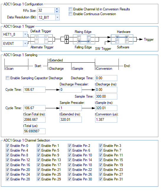
I have set up our HALCoGen project to generate a PWM signal with a 50% duty cycle at a rate of 2000.0us (for 500Hz sampling). I have confirmed this behavior with an oscilloscope. In addition, the ADC1 Group 1 to trigger conversions on the falling edge of pin HET1_8:

Now, the results are interesting. Quite a few times, I have received this error when attempting to re-flash or Debug the application:

I have also seen scenarios, while debugging, where the variables are assigned absurd values in the HAL functions:

In the above image, count is set at FFFFFF40, which would produce an unreasonably long loop and stall code execution. In this scenario, I would expect count to equal 32 (because I have enabled 32 A/D pins). Also, the variable intcr_reg is 224 (which is why count is FFFFFF40). This again seems like an unreasonable value, after reading through the TRM. 

Additionally, I have seen scenarios where GxINTCR[group] value is never changed (and thus no sampling takes place). Sometimes, the code works perfectly. 

In each of these scenarios that I describe, no changes have been made to the code at all. I've simply re-programmed the device with the same binary image. Any ideas why?

A quick aside, we are using SafeRTOS in our project. Could this potentially have some sort of conflict? Perhaps with the prioritization of interrupts? Prior to testing this hardware trigger source, we were using software triggering through an RTOS timer, and this method did not have any bugs that we could see.

Thank you,

James

  • Hello,

    The GxINTCR[1] value is initialized to the FIFO size. The value should increment for each read (fifo mode). Before starting ADC sampling, the FIFO size (32) should be assigned to GxINTCR[1]: GxINTCR[1] = 32. This register is cleared by the NHET interrupt which triggers ADC sampling in your code.

    I am not familiar to safeRTOS.

  • Hello QJ,

    The GxINTCR[1] value is being initialized to the FIFO size. My application code initializes the ADC/NHET in the following order:

    adcInit() 

    adcEnableNotification()

    adcStartConversion() (this is the function that initializes the GxINTCR[1] to the FIFO size)

    hetInit()

    As for SafeRTOS, it places itself in the VIM table at channel 2 (RTI Compare0 interrupt) and channel 21. This prevents our application from utilizing the RTI compare interrupt functionality - if possible, we would use the RTI notification to schedule ADC conversions, and hence why we are using the N2HET.

    Thanks,

    James

  • Hello,

    Is it possible that adcStartConversion() is not executed. The RTI compare0 may be used as the system timer, so you can use compare1 to trigger ADC conversion.

  • Hello QJ,

    adcStartConversion() is certainly executed. As for RTI, SafeRTOS recommends against touching RTI, so we have not experimented with using compare1. Triggering ADC conversion with N2HET is currently our preference. 

    Thank you,

    James

  • Hi James,

    Yes, you can use the rising/falling edge of GIO or NHET signal to trigger the ADC conversion. The issue you got is related to safeRTOS.