This thread has been locked.

If you have a related question, please click the "Ask a related question" button in the top right corner. The newly created question will be automatically linked to this question.

CCS/TM4C1294NCPDT: CCS/TM4C1294

Part Number: TM4C1294NCPDT

Tool/software: Code Composer Studio

Hey, 

I am trying to use TM4C1294's ADC. I am giving a analog voltage as input and when reading the ADC output as an integer. 

How is that conversion happening ? 

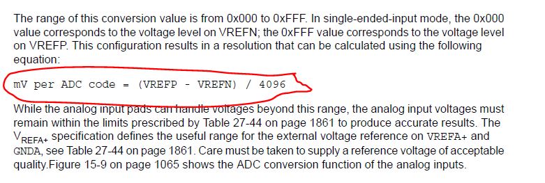
The datasheet provides only the x-axis value for the voltage.

Can you help with how the calculation of the coversion from analog to digital is done ?

It would be helpful if you can share any examples.

Regards, 

Srinivasan.

  • Since you did not give me the particulars of your application, I will give you an example. Assume VREFN is at GND (0V) and VREFP is at 3.3V. 

        float volt;
        unsigned int array[8];
        ...
        //Read ADC input
        ADCSequenceDataGet(ADC0_BASE,3,array); //read the digital voltage value
        volt = ((array[0] * 3.3)/4096); //converting digital value to voltage
    

  • Hey back,

    Several of our young staffers (also) thought a 'chart' and/or 'X vs. Y' representation would prove useful.    (i.e. Boost understanding)

    Following produced in your behalf...

    The conversion occurs via the 'Successive Comparing' of the (external) signal input to the ADC vs. (versus) the ADC's full-scale reference range.   (above 'X-Y chart employed 3300mV as the ADC's full-scale range.)  Twelve such (effective) comparisons are performed sequentially - each one 'Setting' (or clearing) that specific ADC Data bit - based upon the signal input's voltage level.