This thread has been locked.

If you have a related question, please click the "Ask a related question" button in the top right corner. The newly created question will be automatically linked to this question.

TM4C123GH6PM: CAN EWARN EPASS Bit 0 Error on RX

Part Number: TM4C123GH6PM
Other Parts Discussed in Thread: SN65HVD230, EK-TM4C123GXL, SYSCONFIG

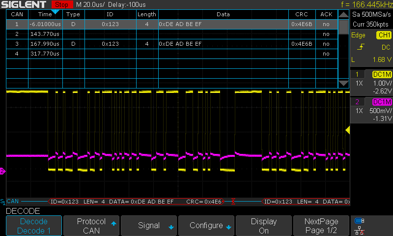
I currently have the launchpad connected to a WaveShare CAN device stuck in a breadboard.  It seems to have a 120 ohm resistor on it and the other 120ohm resistor is on the other side of the cable.  The other end of the cable is plugged into a PEAK USB to CAN adapter.  Both sides are setup at 500k and I use the cansend command on my PC to send 123#DEADBEEF.  However upon hearing this the TM4C begins repeating as fast as it can: "CAN interrupt 0x8000 0x65" I think indicating that there was a Bit 0 error.

Searching around I found:
Check your resistors - Good, pretty sure
Check your bitrates - Good
Scope CANH and CANRX - Both can be decoded by my scope

Does anyone have any ideas?

This is my CAN code in it's entirety right now.  The pin setup is done by pinmux.

#include <stdbool.h>

#include <xdc/std.h>
#include <xdc/runtime/Error.h>
#include <xdc/runtime/System.h>

#include <ti/sysbios/hal/Hwi.h>

#include <inc/hw_memmap.h>
#include <inc/hw_ints.h>
#include <inc/hw_can.h>

#include <driverlib/can.h>
#include <driverlib/interrupt.h>
#include <driverlib/sysctl.h>

#include "candrv.h"

#define CAN0RXID 0
#define RXOBJECT 1

static tCANMsgObject RxMessage;
static uint8_t RxMsgData[8];

void CanDriverHwiHandler(UArg a0)
{
    uint32_t status;
    uint32_t errStatus = 0;
    System_printf("CAN HWI Handler called\n");
    System_flush();

    status = CANIntStatus(CAN0_BASE, CAN_INT_STS_CAUSE);
    if (status == CAN_INT_INTID_STATUS)
    {
        errStatus = CANStatusGet(CAN0_BASE, CAN_STS_CONTROL);
    }
    CANIntClear(CAN0_BASE, status);


    System_printf("CAN interrupt 0x%x 0x%x\n", status, errStatus);
    System_flush();
}

void CreateRtosPrimitives()
{
    Hwi_Handle hwi;
    Error_Block eb;

    Error_init(&eb);

    hwi = Hwi_create(INT_CAN0, CanDriverHwiHandler, NULL, &eb);
    if (hwi == NULL)
    {
        System_abort("Can't create HWI for CAN\n");
    }

    System_printf("Successfully Created primitives for CAN\n");
    System_flush();
}

void InitCanDriver()
{
    CreateRtosPrimitives();
    SysCtlPeripheralEnable(SYSCTL_PERIPH_CAN0);

    CANInit(CAN0_BASE);
    CANBitRateSet(CAN0_BASE, SysCtlClockGet(), 500000);
    CANIntEnable(CAN0_BASE, CAN_INT_MASTER | CAN_INT_ERROR | CAN_INT_STATUS);
    CANEnable(CAN0_BASE);

    System_printf("CAN0 Enabled\n");
    System_flush();

    RxMessage.ui32MsgID = CAN0RXID;
    RxMessage.ui32MsgIDMask = 0;
    RxMessage.ui32Flags = MSG_OBJ_RX_INT_ENABLE | MSG_OBJ_USE_ID_FILTER;
    RxMessage.ui32MsgLen = sizeof(RxMsgData);
    RxMessage.pui8MsgData = RxMsgData;

    CANMessageSet(CAN0_BASE, RXOBJECT, &RxMessage, MSG_OBJ_TYPE_RX);
}

  • Can you be specific about the WaveShare board? Is it the SN65HVD230 CAN Board?

    Which RTOS are you using? I am not aware of a CAN driver in TIRTOS TIVAC 2.16.00.08.

    Can you catch the first CAN frame sent by the PC after the EK-TM4C123GXL has been reset? Look closely and verify if the TM4C has acknowledged the frame. The Bit 0 error means that the CAN module intended to drive CAN TX low, but did not see a corresponding low on CAN RX. When sending a frame from the PC, the only low driven by the TM4C would be the acknowledge bit. It would be best to put the scope probes on the EK-TM4C123GXL CAN TX and CAN RX pins. If this does not make sense, try attaching a scope shot of the first CAN frame.

  • Hi Bob, thanks for the quick support.

    Yes it is the SN65HVD230 board.

    Yea, TIVAC is also not compatible with pinmux so instead I am using TI-RTOS Kernel (SYS/BIOS) and driverlib.  Fancy API y'all built in TIVAC just not useful for this project.

    I don't think the TM4C is acknowledging the frame.  So says the protocol analyzer on my scope and I think wireshark captures a frame where Linux complains about this.  As well there doesn't seem to be RX line involvement on the scope (pink).  It doesn't bother decoding the payload of an ERR frame (0x00 30 00 00 00 00 00 00) but no ACK has a similar number in the kernel.

  • Would you please clarify if the pink RX signal is at the EK-TM4C123GXL CAN RX pin? If that is the case, you have a hardware problem. Which pins on the EK-TM4C123GXL are you using for CAN0RX and CAN0TX?

  • I use PE4 for RX and PE5 for TX.  On the scope yellow is RX and pink is TX.

    I was just reading the transceiver's docs,  am I supposed to be pulling TX up and letting the mcu yank it down to TX?

  • Adam Parker said:
    I use PE4 for RX and PE5 for TX

    OK, that makes sense. The CAN TX pin is push-pull, it should not need a pullup resistor. It looks like the pin did not get properly configured. Can you share your code that does the configuration for PE4 and PE5?

  • So I learned a new trick last night.  I went on the cloud pinmux utility, configured what I needed and saved the result to a local file in the root of my project.  When I went back into CCS it said "Oh, I added your pinmux to the project would you like me to generate code base on it?"  to which I said okay.  It even helpfully had a local GUI which I moved some GPIO around with.  Unfortunately that's my answer on code.  I have a pinmux file that I update through the GUI in CCS.

    I call PinoutSet() from main and that function is apparently generated by the CCS pinmux utility.  I have CCS 9.3 and have been duteous about keeping it up to date.

  • The pinmux tool should have generated a pinout.c file. It should contain the function PinoutSet. Can you find that in your workspace?

  • So I'm not around the computer with that source.  I created a dummy project, threw in a pinmux file (sysconfig is the actual one doing the work apparently).  It hides the source in "Generated Source" and then doesn't bother populating until you compile but once I figured that out I got this out of it.  Again, this isn't my current project but it looks typical to what I'm used to seeing.  I will confirm later that it matches.

    void
    PinoutSet(void)
    {
        //
        // Enable Peripheral Clocks 
        //
    	MAP_SysCtlPeripheralEnable(SYSCTL_PERIPH_GPIOE);
    
        //
        // Configure the GPIO Pin Mux for PE4
    	// for CAN0RX
        //
    	MAP_GPIOPinConfigure(GPIO_PE4_CAN0RX);
    	MAP_GPIOPinTypeCAN(GPIO_PORTE_BASE, GPIO_PIN_4);
    
        //
        // Configure the GPIO Pin Mux for PE5
    	// for CAN0TX
        //
    	MAP_GPIOPinConfigure(GPIO_PE5_CAN0TX);
    	MAP_GPIOPinTypeCAN(GPIO_PORTE_BASE, GPIO_PIN_5);
    
    }

  • Yes, that is similar to what I got of the pinmux tool. It differs from the "simple_rx.c" example in TivaWare (C:\ti\TivaWare_C_Series-2.1.4.178\examples\peripherals\can) in that the two calls to GPIOPinTypeCAN() are combined into a single call. Looking at the source of those functions, it looks like the second call to GPIOPinTypeCAN() which is supposed to configure the TX pin, is undoing the configuration for the RX pin. Try replacing those two calls with the single line:

        GPIOPinTypeCAN(GPIO_PORTE_BASE, GPIO_PIN_4 | GPIO_PIN_5);
    

    If that solves the problem, I will put in a ticket that the pinmux tool needs to be fixed. 

  • Here is a simple CAN RX routine that you can use as a check on the hardware and as a reference.

    /cfs-file/__key/communityserver-discussions-components-files/908/DK_2D00_CAN_5F00_simple_5F00_RX.zip

  • Changing the pin settings to a single line did not fix my issue.  As well the DK-CAN_simple_RX project is not driving the TX line either.

    I placed an order for a new launchpad in hopes this one is just hurt.

  • Hi Adam,

      Bob is out of office for the rest of the week. As suspected by Bob, there could be hardware issue on the board. Please let us know if the new board makes a difference.

  • Hi Charles,

    The new board behaves in the exact same manner unfortunately.

    I guess I will continue to develop the project to include transmitting code.  Maybe that will narrow the problems.  Anything else to test would be greatly appreciated.

     Thanks,

    Adam

  • Hi Adam,

      Did you have a chance to try the simple_rx.c and simple_tx.c examples? They are found in <TivaWare_Installation>/examples/peripherals/can directory. These are proven examples. You can configure one launchpad to do the TX and another launchpad to do the RX. If you can get this to work then I think it will help you debug your current problem. 

     For two nodes with short distance it is even possible to use the diode in place of the CAN transceiver. Below is an example diagram. 

  • Hi,

    I created a project using the mentioned example .c file.  I started with the hello example and replaced the source file with the one from the example.  It still doesn't seem to move the transmit line on transmit.  I have tried it both with a TM4C with the diode setup and with a transceiver connected to a PEAK CAN to USB adapter.

    I would greatly appreciate if you could take a look and see what I have done wrong.

    simple_can_tx.zip

  • Hi Adam,

      I don't spot anything wrong with your code. It is pretty much the TivaWare example. The only difference as I glance through is that you have both the CAN0 and CAN1 mapped to the same CANIntHandler() vector in the startup_ccs.c file. However, I don't think this should create the problem as you are not using CAN1 at the moment. I need to talk to Bob to see if he has other ideas. 

  • Adam,

    I took your project and ran it on my EK-TM4C123GXL launchpad. I had to change the include file path and library paths as your paths were not standard. It runs on my launchpad.

    Would you please provide scope or logic analyzer shots of both PB4 and PB5? Note that if PB4 (CAN0 RX) is low, you will not get anything out of PB5 (CAN0 TX).