This thread has been locked.

If you have a related question, please click the "Ask a related question" button in the top right corner. The newly created question will be automatically linked to this question.

TM4C1294NCPDT: I2C master pull SCL low and won't recover

Part Number: TM4C1294NCPDT

Hi e2e,

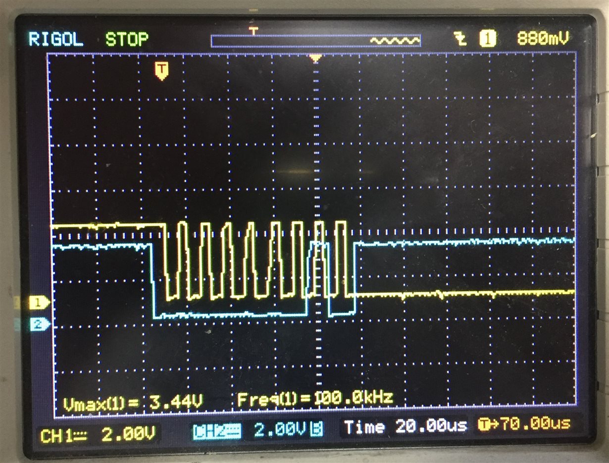
Here we have a customer using TM4C1294 I2C as master, the slave are sensors and other MCU, they meet a problem that the SCL will pull low and the 9th SCL is not sent out, below shows the register while error coming out.

We are very confused that why the 9th SCL is not sending out, what's the status of this condition, need your help, thanks in advance.

  • Hello Lei,

    This potentially could be a case of clock stretching. Does the SCL line ever get released to be high later? How many slave devices are on the bus, and what are the values of the pull up resistors used?

    Details on clock stretching: I2C devices can slow down communication by stretching SCL: During an SCL low phase, any I2C device on the bus may additionally hold down SCL to prevent it from rising again, enabling it to slow down the SCL clock rate or to stop I2C communication for a while. This is also referred to as clock synchronization.

  • Greetings,

    May we ask you to note the, "Frequency of this SCL pulling low condition?"     (i.e. does this occur 'always' or only 'some times?')      While not described - this is believed of value.

    Your subject line notes that the, "Master (the MCU) pulls low!"      Yet there appears no description as to how that conclusion was reached/confirmed?    In addition - no mention of the (required) pull-up resistors (ideally external) appears...

    As always - does this condition occur upon (several) other MCU boards?    My  group has enjoyed sufficient success w/this vendor's MCUs (in I2C mode) to, "Doubt that the MCU - by itself - proves Guilty!"

  • Hi Ralph and cb1,

    thanks for your help, below are replies.

    the SCL line never get released to be high in this condition, pull up resistor is 1.5K.

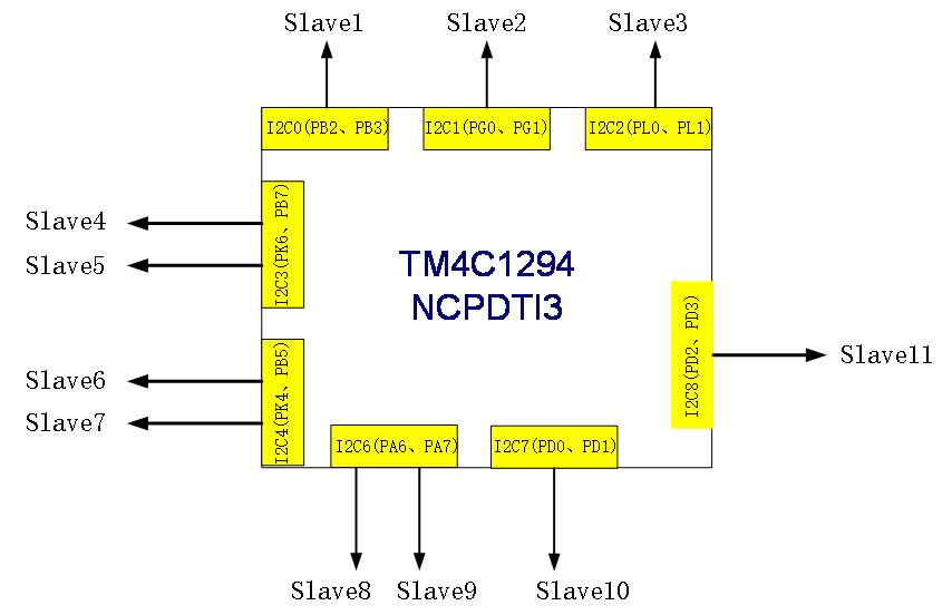
    below is the i2c system.

    it occurs sometimes.

    and there is a serial resistor between master and slave, we removed the resister to check the pull down source, it was done by master.

    there have 1.5K pull up resister in master side.

    Yes, we test several boards, all have this issue.

    does there have any register to help on the issue in TM4C1294?

    thanks.

  • Hello,

    My small group is surprised by your drawing - never have we seen (over a 20+ year period) such an 'I2C' implementation!      (i.e. in which the (assumed) remote Slave devices are NOT attached/routed via the (common) I2C bus - but are instead connected directly to 'differing I2C instantiations' (ports) w/in your (single) MCU.)

    It must be asked:

    • what was your reason for, 'Rejecting the 'normal/customary' I2C bus' - which is able to 'daisy-chain' connect - to multiple I2C Slaves?
    • you show (via the Scope Cap) one master to slave connection - yet your MCU (appears) to be serving as, "Master to Eleven (NON-BUSSED) I2C Slaves!"    Which one of those ELEVEN unique I2C connections (channels) is failing?
    • did you (really) intend to attach your MCU (UNIQUELY) to each Slave?    As an I2C Slave device CANNOT Initiate communications back to the Master - there appears to be 'NO ADVANTAGE' to such an (unexpected) system design. 

    It is suspected that your drawing does NOT (really) reflect the 'reality' of your I2C bus and its (likely) Daisy-Chain connections.    (Staff will diagram a daisy-chain upon arrival tomorrow (Sat) morning...)

    Here is a, 'FAR more typical/expected I2C bus:'

  • Hello Lei,

    I'll be honest, I haven't found anything that would point to a root cause or a similar case to this before, so I am not entirely sure what is going on off the top of my head.

    Based on this unusual application of I2C as cb1 highlighted, the first thought that comes to mind is that some interrupt is interfering with the I2C output and causes this issue.

    Which I2C channels show this issue? Are all the slaves the same device?

    Have there been attempts to recover from the low line state beyond resetting the MCU? Does a peripheral reset work? What happens when trying to send more data?

    Just trying to get some more data points to think through here.

  • Second Greetings,

    LEI YAN said:
    ... using TM4C1294 I2C as Master, the slave(s) are sensors and other MCU, they meet a problem that the SCL will pull low and the 9th SCL is not sent out

    A few days earlier we provided a group of questions in the attempt to assist.    It was (especially) noted that your diagram appeared "unusual" - as I2C is usually employed as a 'Serial Bus' - with (other) I2C devices more simply 'attached' to the common bus.     Your design however revealed each/every 'I2C channel' as being 'composed of (only) TWO Devices' (with a single TM4C MCU as "I2C Central") - again while this can work - it runs contrary to the 'normal/customary' I2C BUS implementations.     (for example - with only 2 I2C devices connected - the use of I2C 'addresses' (which remains required) - serves minimal (no) purpose!)

    Our earlier group of questions remains - yet in further review of your scope cap it appears that:

    • a Slave I2C address of 0x01 is being sent from the TM4C129 Master to the (assumed single) Slave.
    • yet - to my group's knowledge - such an address (0x01) proves 'highly unusual' (possibly illegal) - might the Master MCU (somehow) detect this - and 'clamp down' the SCL line?
    • the scope cap provided - and the writing - fails to advise or inform as to, "Where in the I2C sequence" this, "Lock of SCL" occurs.   That knowledge would be indeed helpful.   (i.e. is this the first transmission to the Slave - or one made after one or more 'successful' I2C data exchanges?)
    • would it not prove (more) useful - instead of sending "0x01" - to send the (known good) address of a 'real Slave' (of course w/that 'real Slave' connected) - and then determine if that transmission eliminates the 'Lock down' of SCL?

    A further thought - might the attached slave (even though you cleverly deployed series resistors) have "Fed back a voltage spike to the MCU Master" - causing it to, "Disable or otherwise disturb the I2C's SCL Output?"    To test for the likelihood of this theory you may:

    • monitor the MCU's Reset Line paying special attention at/around the moment in time when SCL drives (and remains) Low
    • monitor the voltage across the series resistor placed upon 'SCL' and between the Master MCU and Slave
    • employ your Master MCU's 'I2C Filtering' - gradually increasing its effect - to determine if this reduces (or ideally eliminates) SCL's driving (and remaining) low

    Should your drawing accurately reflect your "Many unique (Non-Bussed) I2C Channels" - the powering of each/every one of the slaves (sensor, MCU and/or Slave Board) must be examined.   If different power supplies (or batteries) are employed for (some) Slaves and/or Slave Boards (and your 'Central TM4C129 Hub') - then it proves likely that a 'Common Ground Connection' must be created (or maintained) between each Slave Board and the "Central MCU 'Hub' (per your diagram)."

    Again - we really would benefit from knowing if your drawing (Non-Bussed I2C Channels) is accurate - and if so - how & why that method (rather than the standard, daisy-chained, I2C Bus) was chosen?