Tool/software: Code Composer Studio
HI,
I am working Communication protocol , Using UART1(RS 485) for communicating with external device. I have checked loop back , TX and RX configuration done successfully because getting loop back character. when i sending data to external device UART1 transmitting data successfully, External device HMI display the data which have received from UART1(TM4C123GXL). If i am sending data through HMI , i couldnt get data in TM4C123gxl side. Last two days i hardly working for find this mistake,if any given solution its very helpful for me.
Here i have my sending and receiving code:
//*****************************************************************************
#include <stdint.h>
#include <stdbool.h>
#include "inc/hw_ints.h"
#include "inc/hw_memmap.h"
#include "driverlib/debug.h"
#include "driverlib/fpu.h"
#include "driverlib/gpio.h"
#include "driverlib/interrupt.h"
#include "driverlib/pin_map.h"
#include "driverlib/rom.h"
#include "driverlib/sysctl.h"
#include "driverlib/uart.h"
unsigned char BUF1[100]={'S','N','G'}; // Sending Data
unsigned char BUF2[100];
unsigned int i;
#define RS485base GPIO_PORTA_BASE
#define MAX485_DE GPIO_PIN_6
#define MAX485_RE_NEG GPIO_PIN_7
//*******************************
//*****************************************************************************
#ifdef DEBUG
void
__error__(char *pcFilename, uint32_t ui32Line)
{
}
#endif
//******************************
void preTransmission();
void postTransmission();
//*****************************************************************************
void UART0_put_char(const uint8_t pui8Buffer)
{
preTransmission();
// Write the next character to the UART.
//
UARTCharPut(UART0_BASE, pui8Buffer);
postTransmission();
}
//////////////////////////////////////////////////////////////////////////////////////////////////////////////////
//UART 1 Transmitting Function
void uart1_put_char( uint8_t BUF3 )
{
preTransmission();
UARTCharPut(UART1_BASE, BUF3);
postTransmission();
}
////////////////////////////// //UART 1Recieving Function
void uart1_get_char()
{
postTransmission();
unsigned char j=0;
while(ROM_UARTCharsAvail(UART1_BASE))
{
BUF2[j]=UARTCharGet(UART1_BASE);
UART0_put_char(BUF2[j]);
SysCtlDelay(2000);
j++;
preTransmission();
}
int k;
for(k=0;k<j;k++)
{
BUF2[k]=0;
}
}
//////////////////////////////////////////////////////////////////////////////////////////////////////
void preTransmission()
{
GPIOPinWrite(GPIO_PORTA_BASE, MAX485_RE_NEG, MAX485_RE_NEG);
GPIOPinWrite(GPIO_PORTA_BASE, MAX485_DE, MAX485_DE);
}
void postTransmission()
{
GPIOPinWrite(GPIO_PORTA_BASE, MAX485_RE_NEG, 0x00);
GPIOPinWrite(GPIO_PORTA_BASE, MAX485_DE, 0x00);
}
void RS485enable()
{
SysCtlPeripheralEnable(SYSCTL_PERIPH_GPIOA);
GPIOPinTypeGPIOOutput(RS485base, MAX485_DE|MAX485_RE_NEG);
}
//*****************************************************************************
int main(void)
{
//unsigned char pui8Buffer;
// Enable lazy stacking for interrupt handlers. This allows floating-point
// instructions to be used within interrupt handlers, but at the expense of
// extra stack usage.
//
ROM_FPUEnable();
ROM_FPULazyStackingEnable();
//
// Set the clocking to run directly from the crystal.
//
ROM_SysCtlClockSet(SYSCTL_SYSDIV_1 | SYSCTL_USE_OSC | SYSCTL_OSC_MAIN |
SYSCTL_XTAL_16MHZ);
//
// Enable the GPIO port that is used for the on-board LED.
//
ROM_SysCtlPeripheralEnable(SYSCTL_PERIPH_GPIOF);
//
// Enable the GPIO pins for the LED (PF2).
//
ROM_GPIOPinTypeGPIOOutput(GPIO_PORTF_BASE, GPIO_PIN_2);
//
// Enable the peripherals used by this example.
//
ROM_SysCtlPeripheralEnable(SYSCTL_PERIPH_UART0);
ROM_SysCtlPeripheralEnable(SYSCTL_PERIPH_GPIOA);
ROM_SysCtlPeripheralEnable(SYSCTL_PERIPH_UART1);
ROM_SysCtlPeripheralEnable(SYSCTL_PERIPH_GPIOB);
//
// Enable processor interrupts.
//
// ROM_IntMasterEnable();
//
// Set GPIO A0 and A1 as UART pins.
//
GPIOPinConfigure(GPIO_PA0_U0RX);
GPIOPinConfigure(GPIO_PA1_U0TX);
GPIOPinConfigure(GPIO_PB0_U1RX);
GPIOPinConfigure(GPIO_PB1_U1TX);
ROM_GPIOPinTypeUART(GPIO_PORTA_BASE, GPIO_PIN_0 | GPIO_PIN_1);
ROM_GPIOPinTypeUART(GPIO_PORTB_BASE, GPIO_PIN_0 | GPIO_PIN_1);
//
// Configure the UART for 115,200, 8-N-1 operation.
//
ROM_UARTConfigSetExpClk(UART0_BASE, ROM_SysCtlClockGet(),19200,
(UART_CONFIG_WLEN_8 | UART_CONFIG_STOP_ONE |
UART_CONFIG_PAR_NONE));
ROM_UARTConfigSetExpClk(UART1_BASE, ROM_SysCtlClockGet(), 19200,
(UART_CONFIG_WLEN_8 | UART_CONFIG_STOP_ONE |
UART_CONFIG_PAR_NONE));
RS485enable();
// Loop forever echoing data through the UART.
//
GPIOPinWrite(GPIO_PORTA_BASE, GPIO_PIN_6, 0x00);
GPIOPinWrite(GPIO_PORTA_BASE, GPIO_PIN_7, 0x00);
while(1)
{
uint32_t value=0;
uint8_t i=0;
for(i=0;i<6;i++)
{
uart1_put_char( BUF1[i]); // Transmitting Data
}
uart1_get_char(); // Receiving Data
}
}
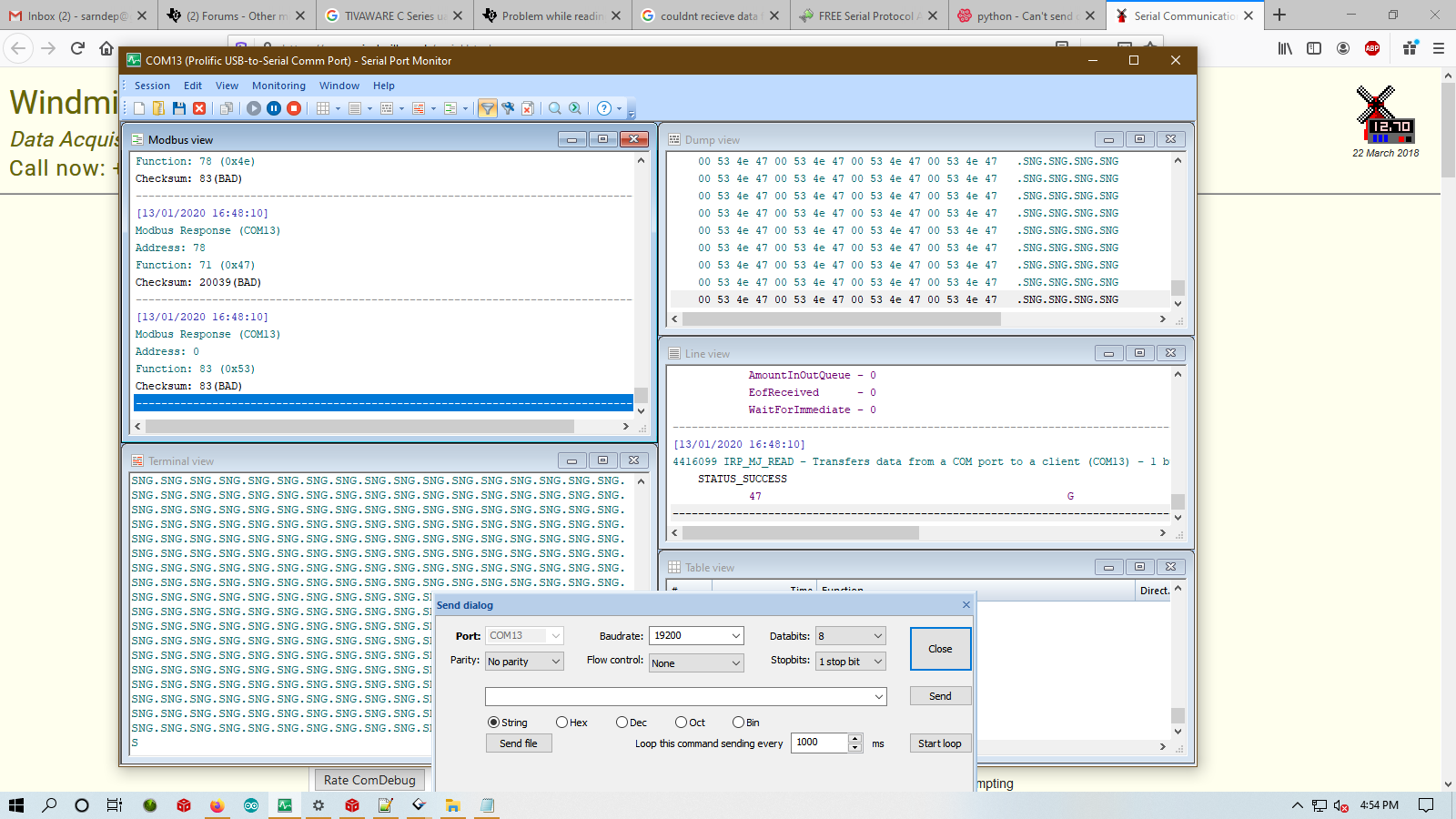
Serial Monitor Output window