This thread has been locked.

If you have a related question, please click the "Ask a related question" button in the top right corner. The newly created question will be automatically linked to this question.

CCS/TM4C123GH6PM: CAN bus implementation with 2 TM4C123GH6PM is not working

Part Number: TM4C123GH6PM
Other Parts Discussed in Thread: SN65HVD230

Tool/software: Code Composer Studio

Hello,

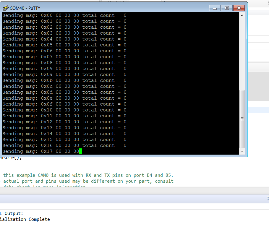
I am using 2 TM4C123GH6PM boards and  CAN0 and UART0 of both the boards. I have taken CAN bus  example from Dk-TM4C123G
board example. I have deleted the LCD part because I don't need this for my testing.
I am using 2 CJMCU-30 transceiver having IC SN65HVD230.
I am not getting output at all.
I have checked hardware connection, they are correct and the code is also error-free
and debugging properly.
I have changed CAN0 pins then also I am not getting
the output.
Please help me to find the solution to this problem

  • Hi,

      Can you try the attached can_simple.tx.c example or compare with your existing one? I assume you have proper termination resistance (i..e. one 120 Ohm resistor at each end of the bus) between the CAN_H and CAN_L. This is especially critical for long distance.   

    //*****************************************************************************
    //
    // simple_tx.c - Example demonstrating simple CAN message transmission.
    //
    // Copyright (c) 2010-2017 Texas Instruments Incorporated.  All rights reserved.
    // Software License Agreement
    // 
    //   Redistribution and use in source and binary forms, with or without
    //   modification, are permitted provided that the following conditions
    //   are met:
    // 
    //   Redistributions of source code must retain the above copyright
    //   notice, this list of conditions and the following disclaimer.
    // 
    //   Redistributions in binary form must reproduce the above copyright
    //   notice, this list of conditions and the following disclaimer in the
    //   documentation and/or other materials provided with the  
    //   distribution.
    // 
    //   Neither the name of Texas Instruments Incorporated nor the names of
    //   its contributors may be used to endorse or promote products derived
    //   from this software without specific prior written permission.
    // 
    // THIS SOFTWARE IS PROVIDED BY THE COPYRIGHT HOLDERS AND CONTRIBUTORS
    // "AS IS" AND ANY EXPRESS OR IMPLIED WARRANTIES, INCLUDING, BUT NOT
    // LIMITED TO, THE IMPLIED WARRANTIES OF MERCHANTABILITY AND FITNESS FOR
    // A PARTICULAR PURPOSE ARE DISCLAIMED. IN NO EVENT SHALL THE COPYRIGHT
    // OWNER OR CONTRIBUTORS BE LIABLE FOR ANY DIRECT, INDIRECT, INCIDENTAL,
    // SPECIAL, EXEMPLARY, OR CONSEQUENTIAL DAMAGES (INCLUDING, BUT NOT
    // LIMITED TO, PROCUREMENT OF SUBSTITUTE GOODS OR SERVICES; LOSS OF USE,
    // DATA, OR PROFITS; OR BUSINESS INTERRUPTION) HOWEVER CAUSED AND ON ANY
    // THEORY OF LIABILITY, WHETHER IN CONTRACT, STRICT LIABILITY, OR TORT
    // (INCLUDING NEGLIGENCE OR OTHERWISE) ARISING IN ANY WAY OUT OF THE USE
    // OF THIS SOFTWARE, EVEN IF ADVISED OF THE POSSIBILITY OF SUCH DAMAGE.
    // 
    // This is part of revision 2.1.4.178 of the Tiva Firmware Development Package.
    //
    //*****************************************************************************
    
    #include <stdbool.h>
    #include <stdint.h>
    #include "inc/hw_can.h"
    #include "inc/hw_ints.h"
    #include "inc/hw_memmap.h"
    #include "driverlib/can.h"
    #include "driverlib/gpio.h"
    #include "driverlib/interrupt.h"
    #include "driverlib/pin_map.h"
    #include "driverlib/sysctl.h"
    #include "driverlib/uart.h"
    #include "utils/uartstdio.h"
    
    //*****************************************************************************
    //
    //! \addtogroup can_examples_list
    //! <h1>Simple CAN TX (simple_tx)</h1>
    //!
    //! This example shows the basic setup of CAN in order to transmit messages
    //! on the CAN bus.  The CAN peripheral is configured to transmit messages
    //! with a specific CAN ID.  A message is then transmitted once per second,
    //! using a simple delay loop for timing.  The message that is sent is a 4
    //! byte message that contains an incrementing pattern.  A CAN interrupt
    //! handler is used to confirm message transmission and count the number of
    //! messages that have been sent.
    //!
    //! This example uses the following peripherals and I/O signals.  You must
    //! review these and change as needed for your own board:
    //! - CAN0 peripheral
    //! - GPIO Port B peripheral (for CAN0 pins)
    //! - CAN0RX - PB4
    //! - CAN0TX - PB5
    //!
    //! The following UART signals are configured only for displaying console
    //! messages for this example.  These are not required for operation of CAN.
    //! - GPIO port A peripheral (for UART0 pins)
    //! - UART0RX - PA0
    //! - UART0TX - PA1
    //!
    //! This example uses the following interrupt handlers.  To use this example
    //! in your own application you must add these interrupt handlers to your
    //! vector table.
    //! - INT_CAN0 - CANIntHandler
    //
    //*****************************************************************************
    
    //*****************************************************************************
    //
    // A counter that keeps track of the number of times the TX interrupt has
    // occurred, which should match the number of TX messages that were sent.
    //
    //*****************************************************************************
    volatile uint32_t g_ui32MsgCount = 0;
    
    //*****************************************************************************
    //
    // A flag to indicate that some transmission error occurred.
    //
    //*****************************************************************************
    volatile bool g_bErrFlag = 0;
    
    //*****************************************************************************
    //
    // This function sets up UART0 to be used for a console to display information
    // as the example is running.
    //
    //*****************************************************************************
    void
    InitConsole(void)
    {
        //
        // Enable GPIO port A which is used for UART0 pins.
        // TODO: change this to whichever GPIO port you are using.
        //
        SysCtlPeripheralEnable(SYSCTL_PERIPH_GPIOA);
    
        //
        // Configure the pin muxing for UART0 functions on port A0 and A1.
        // This step is not necessary if your part does not support pin muxing.
        // TODO: change this to select the port/pin you are using.
        //
        GPIOPinConfigure(GPIO_PA0_U0RX);
        GPIOPinConfigure(GPIO_PA1_U0TX);
    
        //
        // Enable UART0 so that we can configure the clock.
        //
        SysCtlPeripheralEnable(SYSCTL_PERIPH_UART0);
    
        //
        // Use the internal 16MHz oscillator as the UART clock source.
        //
        UARTClockSourceSet(UART0_BASE, UART_CLOCK_PIOSC);
    
        //
        // Select the alternate (UART) function for these pins.
        // TODO: change this to select the port/pin you are using.
        //
        GPIOPinTypeUART(GPIO_PORTA_BASE, GPIO_PIN_0 | GPIO_PIN_1);
    
        //
        // Initialize the UART for console I/O.
        //
        UARTStdioConfig(0, 115200, 16000000);
    }
    
    //*****************************************************************************
    //
    // This function provides a 1 second delay using a simple polling method.
    //
    //*****************************************************************************
    void
    SimpleDelay(void)
    {
        //
        // Delay cycles for 1 second
        //
        SysCtlDelay(16000000 / 3);
    }
    
    //*****************************************************************************
    //
    // This function is the interrupt handler for the CAN peripheral.  It checks
    // for the cause of the interrupt, and maintains a count of all messages that
    // have been transmitted.
    //
    //*****************************************************************************
    void
    CANIntHandler(void)
    {
        uint32_t ui32Status;
    
        //
        // Read the CAN interrupt status to find the cause of the interrupt
        //
        ui32Status = CANIntStatus(CAN0_BASE, CAN_INT_STS_CAUSE);
    
        //
        // If the cause is a controller status interrupt, then get the status
        //
        if(ui32Status == CAN_INT_INTID_STATUS)
        {
            //
            // Read the controller status.  This will return a field of status
            // error bits that can indicate various errors.  Error processing
            // is not done in this example for simplicity.  Refer to the
            // API documentation for details about the error status bits.
            // The act of reading this status will clear the interrupt.  If the
            // CAN peripheral is not connected to a CAN bus with other CAN devices
            // present, then errors will occur and will be indicated in the
            // controller status.
            //
            ui32Status = CANStatusGet(CAN0_BASE, CAN_STS_CONTROL);
    
            //
            // Set a flag to indicate some errors may have occurred.
            //
            g_bErrFlag = 1;
        }
    
        //
        // Check if the cause is message object 1, which what we are using for
        // sending messages.
        //
        else if(ui32Status == 1)
        {
            //
            // Getting to this point means that the TX interrupt occurred on
            // message object 1, and the message TX is complete.  Clear the
            // message object interrupt.
            //
            CANIntClear(CAN0_BASE, 1);
    
            //
            // Increment a counter to keep track of how many messages have been
            // sent.  In a real application this could be used to set flags to
            // indicate when a message is sent.
            //
            g_ui32MsgCount++;
    
            //
            // Since the message was sent, clear any error flags.
            //
            g_bErrFlag = 0;
        }
    
        //
        // Otherwise, something unexpected caused the interrupt.  This should
        // never happen.
        //
        else
        {
            //
            // Spurious interrupt handling can go here.
            //
        }
    }
    
    //*****************************************************************************
    //
    // Configure the CAN and enter a loop to transmit periodic CAN messages.
    //
    //*****************************************************************************
    int
    main(void)
    {
    #if defined(TARGET_IS_TM4C129_RA0) ||                                         \
        defined(TARGET_IS_TM4C129_RA1) ||                                         \
        defined(TARGET_IS_TM4C129_RA2)
        uint32_t ui32SysClock;
    #endif
    
        tCANMsgObject sCANMessage;
        uint32_t ui32MsgData;
        uint8_t *pui8MsgData;
    
        pui8MsgData = (uint8_t *)&ui32MsgData;
    
        //
        // Set the clocking to run directly from the external crystal/oscillator.
        // TODO: The SYSCTL_XTAL_ value must be changed to match the value of the
        // crystal on your board.
        //
    #if defined(TARGET_IS_TM4C129_RA0) ||                                         \
        defined(TARGET_IS_TM4C129_RA1) ||                                         \
        defined(TARGET_IS_TM4C129_RA2)
        ui32SysClock = SysCtlClockFreqSet((SYSCTL_XTAL_25MHZ |
                                           SYSCTL_OSC_MAIN |
                                           SYSCTL_USE_OSC)
                                           25000000);
    #else
        SysCtlClockSet(SYSCTL_SYSDIV_1 | SYSCTL_USE_OSC | SYSCTL_OSC_MAIN |
                       SYSCTL_XTAL_16MHZ);
    #endif
    
        //
        // Set up the serial console to use for displaying messages.  This is
        // just for this example program and is not needed for CAN operation.
        //
        InitConsole();
    
        //
        // For this example CAN0 is used with RX and TX pins on port B4 and B5.
        // The actual port and pins used may be different on your part, consult
        // the data sheet for more information.
        // GPIO port B needs to be enabled so these pins can be used.
        // TODO: change this to whichever GPIO port you are using
        //
        SysCtlPeripheralEnable(SYSCTL_PERIPH_GPIOB);
    
        //
        // Configure the GPIO pin muxing to select CAN0 functions for these pins.
        // This step selects which alternate function is available for these pins.
        // This is necessary if your part supports GPIO pin function muxing.
        // Consult the data sheet to see which functions are allocated per pin.
        // TODO: change this to select the port/pin you are using
        //
        GPIOPinConfigure(GPIO_PB4_CAN0RX);
        GPIOPinConfigure(GPIO_PB5_CAN0TX);
    
        //
        // Enable the alternate function on the GPIO pins.  The above step selects
        // which alternate function is available.  This step actually enables the
        // alternate function instead of GPIO for these pins.
        // TODO: change this to match the port/pin you are using
        //
        GPIOPinTypeCAN(GPIO_PORTB_BASE, GPIO_PIN_4 | GPIO_PIN_5);
    
        //
        // The GPIO port and pins have been set up for CAN.  The CAN peripheral
        // must be enabled.
        //
        SysCtlPeripheralEnable(SYSCTL_PERIPH_CAN0);
    
        //
        // Initialize the CAN controller
        //
        CANInit(CAN0_BASE);
    
        //
        // Set up the bit rate for the CAN bus.  This function sets up the CAN
        // bus timing for a nominal configuration.  You can achieve more control
        // over the CAN bus timing by using the function CANBitTimingSet() instead
        // of this one, if needed.
        // In this example, the CAN bus is set to 500 kHz.  In the function below,
        // the call to SysCtlClockGet() or ui32SysClock is used to determine the 
        // clock rate that is used for clocking the CAN peripheral.  This can be 
        // replaced with a  fixed value if you know the value of the system clock, 
        // saving the extra function call.  For some parts, the CAN peripheral is 
        // clocked by a fixed 8 MHz regardless of the system clock in which case 
        // the call to SysCtlClockGet() or ui32SysClock should be replaced with 
        // 8000000.  Consult the data sheet for more information about CAN 
        // peripheral clocking.
        //
    #if defined(TARGET_IS_TM4C129_RA0) ||                                         \
        defined(TARGET_IS_TM4C129_RA1) ||                                         \
        defined(TARGET_IS_TM4C129_RA2)
        CANBitRateSet(CAN0_BASE, ui32SysClock, 500000);
    #else
        CANBitRateSet(CAN0_BASE, SysCtlClockGet(), 500000);
    #endif
    
        //
        // Enable interrupts on the CAN peripheral.  This example uses static
        // allocation of interrupt handlers which means the name of the handler
        // is in the vector table of startup code.  If you want to use dynamic
        // allocation of the vector table, then you must also call CANIntRegister()
        // here.
        //
        // CANIntRegister(CAN0_BASE, CANIntHandler); // if using dynamic vectors
        //
        CANIntEnable(CAN0_BASE, CAN_INT_MASTER | CAN_INT_ERROR | CAN_INT_STATUS);
    
        //
        // Enable the CAN interrupt on the processor (NVIC).
        //
        IntEnable(INT_CAN0);
    
        //
        // Enable the CAN for operation.
        //
        CANEnable(CAN0_BASE);
    
        //
        // Initialize the message object that will be used for sending CAN
        // messages.  The message will be 4 bytes that will contain an incrementing
        // value.  Initially it will be set to 0.
        //
        ui32MsgData = 0;
        sCANMessage.ui32MsgID = 1;
        sCANMessage.ui32MsgIDMask = 0;
        sCANMessage.ui32Flags = MSG_OBJ_TX_INT_ENABLE;
        sCANMessage.ui32MsgLen = sizeof(pui8MsgData);
        sCANMessage.pui8MsgData = pui8MsgData;
    
        //
        // Enter loop to send messages.  A new message will be sent once per
        // second.  The 4 bytes of message content will be treated as an uint32_t
        // and incremented by one each time.
        //
        while(1)
        {
            //
            // Print a message to the console showing the message count and the
            // contents of the message being sent.
            //
            UARTprintf("Sending msg: 0x%02X %02X %02X %02X",
                       pui8MsgData[0], pui8MsgData[1], pui8MsgData[2],
                       pui8MsgData[3]);
    
            //
            // Send the CAN message using object number 1 (not the same thing as
            // CAN ID, which is also 1 in this example).  This function will cause
            // the message to be transmitted right away.
            //
            CANMessageSet(CAN0_BASE, 1, &sCANMessage, MSG_OBJ_TYPE_TX);
    
            //
            // Now wait 1 second before continuing
            //
            SimpleDelay();
    
            //
            // Check the error flag to see if errors occurred
            //
            if(g_bErrFlag)
            {
                UARTprintf(" error - cable connected?\n");
            }
            else
            {
                //
                // If no errors then print the count of message sent
                //
                UARTprintf(" total count = %u\n", g_ui32MsgCount);
            }
    
            //
            // Increment the value in the message data.
            //
            ui32MsgData++;
        }
    
        //
        // Return no errors
        //
        return(0);
    }
    

  • Greetings,

    You note, 

    Deoyani Joshi said:
    I have checked hardware connection, they are correct

    Yet - unknown is your "Experience/Expertise Level wrt CAN" - a schematic drawing would enable "Group Review."

    You further note, "Not getting the output."

    Yet there are multiple outputs - are there not?    (i.e. CAN_TX, and (both) differential signals resident upon the CAN Bus)

    As there are 2 MCUs & 2 CAN XCVRS - there exist (many) points to probe.    (It proves worthwhile to "Test each end of your Dual MCU App!")

    Scope Caps always prove best when diagnosing a "Failing Serial Implementation" - had you monitored (all potential) outputs w/a scope?    If not via a scope - how was the "output" monitored?

  • I have tried simple_tx. and simple_rx  from tivaware peripheral example. this is the same example that I have tried. 

    I am not getting the output.

    I am new to this board and CAN bus implementation is also new for me is there any setting or hardware issue can you give me any suggestion about how to check it?

    There is a 120-ohm resistor between CAN_H and CAN_L at each end of the bus.

    I am checking output on Serial Terminal (putty).

    thanks for replying me.

    regards

    Deoyani Joshi

  • I have tried simple_tx code again, now  I am getting the following error. I am getting the same output with pin config( PE4-CAN0RX, PE5-CAN0TX, PB4-CAN0RX, PB5-CAN0TX, PF0-CAN0RX, PF3-PE5-CAN0TX)

    "Sending msg: 0x4d 00 00 00 error - cable connected?"

     thanks and regards

    Deoyani 

  • Earlier you reported, "I have checked hardware connection, they are correct."

    A schematic drawing revealing "ALL of your connections" was requested:

    • MCU1 to CAN Xcvr1
    • CANBus1 to CANBus2 (differential signal side)
    • MCU2 to CAN Xcvr2

    Providing this requested information reduces "guesswork" forced upon your 'helpers.'     And gains you "Additional Eyes" to review your hardware connections.   (earlier deemed "correct" by you)

    You most recently report receiving, "Error - cable connected?"    This increases the importance of your (still missing) schematic diagram.

    Note that you earlier reported, "I am checking output on Serial Terminal (putty)."    Yet the output of (most all) CAN Xcvrs is "unlikely" to be compatible w/your (assumed) PC configured as a serial terminal.    (the PC almost surely 'expects' a USB connection - not provided by most all CAN Xcvrs!)

    Unexplained is your action which moved your results from, "No Output" to (now) "Error - cable corrected!"    What had you done to achieve 'this' (first time) new output?

    Scope captures of the earlier listed CAN signal lines (at each MCU & across the CAN Bus) have (not) been supplied.    These prove crucial in "Quick & Eased" remote diagnosis of most any serial bus...

  • Hello,

    I am sending you a rough schematic diagram  these are my connection with transceiver, these are properly connected as CAN0RX to PE4 of TM4C123G

    CAN0TX to PE5 of TM4C123G

    3.3v and GND connections

    and CANL to the other transceiver CANL, CANH to the other transceiver CANH. 

    Are there other connections? 

    Sorry, I don't know much about it. 

    please guide me properly to solve this

    thanks and regards

    Deoyani


  • Thank you.    Following issues remain unclear:

    • How & where did you connect your Serial Terminal?
    • As noted - your Serial Terminal is suspected to be an APP w/in a PC.    Is this correct?
    • Most all modern PCs have eliminated (the past) UARTs - replacing these w/USB ports.    As earlier noted - CAN Xcvrs (unless highly specialized) provide output aimed for UARTs - not for USB.
    • From where did your Error "Cable Connected?" arise?    (i.e. was that error revealed w/in "Simple_rx or Simple_tx?")
    • It appears that you've no access to a Scope - monitoring the CAN Bus proves far harder w/out "scope-caps."   Cannot you borrow a scope or bring your boards to some school - where scopes are available?
    • Have you measured continuity across each of the 2 CAN Bus signal lines (cable)?     You should test for a cable short as well.
    • Is your 2nd CAN Xcvr & MCU connected to a separate (different) PC?    If so - what is the separation distance between CAN locations?
    • As always - when communication fails - it proves best to, "Use the slowest Bus Speed possible."    Only after communication is established should the, "Need for Speed" be entertained.   (attempted)

    Yes many questions - yet the term "No Output" is too vague to be of much use.     "How & Where" 'No Output' was measured would aid greatly...

  • Hello,

    this is UART0 output of one  TM4C123G board in which Simple_tx.c is loaded and in the other board simple_rx.c is loaded and it shows nothing.

    thanks and regards

    Deoyani 

  • Hello 

    while capturing output I have configured  PB4 as RX and PB5 as Tx of CAN0 in the code and on the board,(hardware connection) I have connected PE4 as Rx and PE5 as tx then I am showing this attached output.

    when I connect correct pins  ie 

    PB4-as CAN0RxTM4c123G

     PB5 -CAN0Tx TM4C123G  like 

      I have configured  in the code I am getting  following output

     "Error - cable connected?"

    why this is happening I am not getting it......

    thanks and regards

    Deoyani 

  • Hi,

      If you are seeing "error - cable connected?" printed on the terminal window then the CAN kernel has detected an error. Please find out the status from the CANSTS register to determine the cause of the error. As suggested by cb1, it will be much easier to debug your problem if you have the scope to capture the CAN bus. 

  • Hello Charles,

    How to find out the status from the CANSTS register?

    Can you please guide me properly.

    Thanks and Regards

    Deoyani


  • Hi,

      Please refer to the CANIntHandler() ISR. It is calling the CANIntStatus to find out the cause of the interrupt. This function will read the CANSTS register. You can put a breakpoint at the line to find out the value that is returned from the call or simply browse the register window. 

    void
    CANIntHandler(void)
    {
        uint32_t ui32Status;
    
        //
        // Read the CAN interrupt status to find the cause of the interrupt
        //
        ui32Status = CANIntStatus(CAN0_BASE, CAN_INT_STS_CAUSE);
    
        //
        // If the cause is a controller status interrupt, then get the status
        //
        if(ui32Status == CAN_INT_INTID_STATUS)


  • Hello Charles,

    Thanks - you did an excellent job of guiding poster (and others [especially my small group]) w/this key (insider) detail.

    Neither staff nor myself could find info re: "CAN_INT_STS_CAUSE" - as it was not listed w/in the API's CAN Defines.    We then searched 'pin_map' - again w/out recognition.   

    Digging deeper - we found its description ('buried' w/in the API) - and believe it best to "share" that key find w/poster & interested others:

    This API screen cap (below) illustrates our (and others) difficulty in such critical recognition:

    Do note that (entire staff here) was 'lost' - until our 3rd search (after failed search of pin_map.h & TM4C123 manual) uncovered this (well hidden) eIntStsReg parameter.   (found w/in ONLY the API library.)   As the understanding of this parameter is critical - might it be best to, "More noticeably present it?"    (of course not your job nor were you a cause agent - yet 'hiding' such data is unlikely to 'boost' MCU Sales...)

  • Hi cb1,

      Thank you for your feedback and your presentation of the API function. I also found the below notes in the datasheet that will provide additional clarify to the poster. 

    The interrupt identifier INTID in the CANINT register indicates the cause of the interrupt. When no
    interrupt is pending, the register reads as 0x0000. If the value of the INTID field is different from 0,
    then an interrupt is pending. If the IE bit is set in the CANCTL register, the interrupt line to the
    interrupt controller is active. The interrupt line remains active until the INTID field is 0, meaning
    that all interrupt sources have been cleared (the cause of the interrupt is reset), or until IE is cleared,
    which disables interrupts from the CAN controller.


    The INTID field of the CANINT register points to the pending message interrupt with the highest
    interrupt priority. The SIE bit in the CANCTL register controls whether a change of the RXOK, TXOK,
    and LEC bits in the CANSTS register can cause an interrupt. The EIE bit in the CANCTLregister
    controls whether a change of the BOFF and EWARN bits in the CANSTS register can cause an
    interrupt. The IE bit in the CANCTL register controls whether any interrupt from the CAN controller
    actually generates an interrupt to the interrupt controller. The CANINT register is updated even
    when the IE bit in the CANCTL register is clear, but the interrupt is not indicated to the CPU.
    A value of 0x8000 in the CANINT register indicates that an interrupt is pending because the CAN
    module has updated, but not necessarily changed, the CANSTS register, indicating that either an
    error or status interrupt has been generated. A write access to the CANSTS register can clear the
    RXOK, TXOK, and LEC bits in that same register; however, the only way to clear the source of a
    status interrupt is to read the CANSTS register.


    The source of an interrupt can be determined in two ways during interrupt handling. The first is to
    read the INTID bit in the CANINT register to determine the highest priority interrupt that is pending,
    and the second is to read the CAN Message Interrupt Pending (CANMSGnINT) register to see
    all of the message objects that have pending interrupts.


    An interrupt service routine reading the message that is the source of the interrupt may read the
    message and clear the message object's INTPND bit at the same time by setting the CLRINTPND
    bit in the CANIFnCMSK register. Once the INTPND bit has been cleared, the CANINT register
    contains the message number for the next message object with a pending interrupt.

    The datasheet has the full description of all the error flags and LEC code that match with the API.

  • Hello Charles,

    That's quite a bit of detail - thank you ... yet does not this, "Array of interlocking facts" almost surely, "Force the use of a Scope" for proper CAN Analysis?     As poster has been advised (repeatedly) of the, "Scope's necessity" - his continued 'silence' (regarding the scope) forces EXTRA EFFORT upon all helpers!

    My group has suggested methods for poster to 'borrow or use another's scope' - minus poster's acknowledgement.   

    As this fresh detail well notes - CAN is a "très serious" Bus - thus highly demanding - and almost certain (in time) to "Demand Scope Diagnosis."   (Dare it be noted that its use by the, "Inexperienced and/or Under-Equipped" may 'over-challenge' - and EAT the time/effort of hapless helpers?)

  • Hi cb1,

      Fully agreed with you on the need of the scope to aid the diagnosis as I have mentioned in my Mon, Feb 3 2020 8:41 AM reply.  

  • Indeed Charles - the "EFFECTIVE MENTION" of the "Demand for key Scope Caps" prevents the "unfair" (near abuse) of helpers.

    Often being "EFFECTIVE" demands beyond a 'single mention' - and even, "Suggestions as to, 'How to acquire' a needed device..."