This thread has been locked.

If you have a related question, please click the "Ask a related question" button in the top right corner. The newly created question will be automatically linked to this question.

TMS470MF06607: CAN Transmission

Part Number: TMS470MF06607
Other Parts Discussed in Thread: HALCOGEN,

Hi, I am right  now taping the CAN communication between the sparkfun OBD-II UART board and OBD-II emulator by using the TMDX0MF066USB. I Had  able to  receive the data on CAN bus what is transmitting between two devices but  I have unable to transmit the data. I Had set  the both frematics and the TMS  board to 250 kbps and 11 bit identifier.

as  i observed that sparkfun is sending

(for example) 02 01 0D and emulator is responding with  03 41 32.

But same i am sending from the my TMS controller but I am not getting any response from emulator.

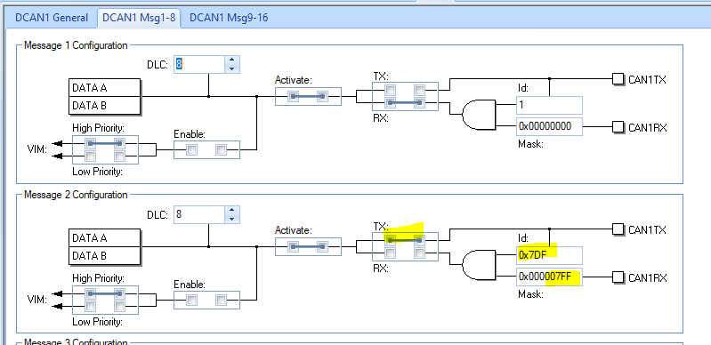
IS their any aditional changes required for TMS to send the data to OBD-II emulator like Message ID given as 7DF for  emulator,if so how to set it? please Help me.

Regards,

Shiva

  • Here is what the HALCoGen looks like for configuring message 2 as a transmit message with 11 bit ID 0x7DF.

    You probably need a logic analyzer with a CAN bus interpreter to make sure you are sending exactly the same message as the sparkfun OBD-II board. 

  • Thanks Bob, for the answer. we got a results.

    i can able to send through my TMS470MF06607 controller also.

    what is m y challenge after this is, if in the freematics i changed from 250kbps/11bit to 500kbps/29bit then i will not get reply, Because my code i generated from Halcogen with 250kbps/11bit. 

    so, in this situation how will set my baud rate of CAN automatically. 

    is there any way to do automatically by software. or every protocol i have change my coding.

    Thanks 

    Anil D.

  • And one more thing i would like to ask like if i would like to check the same test with 500kbps/29bit then 0x7DF will change? and what about mask value. will it be 0x00007FF only or i have change it?

    Thanks,

    Anil D.

  • Changing to 29 bit identifier does not necessarily change the message ID, it can still be 0x7DF. Since the TMS470MF06607 is transmitting, the mask is not used. Just for clarity you can change it to 0x1FFFFFFF.

  • Remember that HALCoGen is just a code generator. You can look at the HALCoGen generated code and see a function canInit (in the file can.c). This function sets the baud rate and the initial mailbox configurations. You can look at how this function sets the baud rate and configures the mailboxes. Or, you can generate separate HALCoGen projects for each configuration. Then copy the canInit() function of the new configuration into the original can.c file, but give it a new name such as canInit500K29() or canInit250K11(). Paste the new functions in between the /* USER CODE BEGIN (3) */ and /* USER CODE END */ (lines 79 and 80) so that they are not lost if you redo the HALCoGen code generation of the original configuration.

  • Hi Bob,

    i tried with 29 bit Identifier with 0x7DF ID and mask is 0x1FFFFFFF value. i am able to receive a data but i can't able to question to frematics. Previously with 11bit Identifier, i got a results. 

    My settings are 

    so by using this settings i tried. i am unable to question to frematics.

    another thing i tried is understand a coding. so i found that in MASK and Arbitration register have changes according to 11 bit or 29 bit Identifier. 

    so mask is for accept a data from CAN using MASK values. so what to accept will decide by MASK register.

    and Arbitration Register is used for Identifier 11 bit or 29 bit and it is a TX or RX used.

    TMS470M Series Technical Reference Manual.pdf

    http://www.ti.com/lit/ug/spnu495c/spnu495c.pdf   page no: 424. 

    so by this study also i am unable to do a auto baud rate. 

    what is mean by Auto baud rate means my single code should work with 250kbps/11bit  or 500kbps/11bit OR 500kbps/29bit OR 250kbps/29bit automatically.  I don't wants to change a coding for that.  Automatic it should happen.

    is this Possible by TMS?

    Thanks,

    Anil D.

  • There is no autobaud feature in the hardware of the DCAN module. You would need to write your own code that detects the proper baud rate and sets the CAN module to that baud rate.

  • okay Bob,

    Thanks for Clarification. If any link to study for algorithm please share.

    Anil D.

  • Greetings,

    Anil Dhanawade said:
    If any link to study for algorithm please share.

    Our (outsider) team believes you'd gain insights from reviewing the means that "UART's employ" to realize, "Auto-Baud" capability.    Far more focused data is available from the "UART perspective" as it has been around longer (than CAN)  & enjoys (still) huge popularity.

    Often the (special) bytes "0xAA or 0x55" are sent for "evaluation" by an attached UART seeking to determine the transmission's baud rate.    The "magic" w/in those two key bytes is their, "Toggling of each data bit" - which, "Speeds, Eases & Enhances" the determination of the UART's baud rate.    (i.e. Eases the measurement of the "width" of the individual data bits.)

    Both your remote & local CAN device must "agree" upon the "conditions under which such 'Auto-Baud Detection' is implemented."   It is only "after" Auto-Baud has succeeded that, "Real CAN channel transactions commence."

    [Added]  there exist places w/in the CAN circuit where a "Scope" can "best examine" (thus measure) those individual data bits.    Identification of those locations is left for the poster/interested reader.    The scope is in "No way required" for the MCU to add such "Auto-Baud" capability.   (mentioned solely to "assist/speed" the process...)

  • Besides measuring the bit width as suggested by CB1 above, you use a "try and check" algorithm. Since OBD-II ISO15765-4 only supports 4 CAN formats, you can try them with the "Silent" bit set and see if you are receiving valid CAN frames. In fact, just try 500K baud 29-bit identifier and see if you are getting CAN errors, or getting valid messages. If you are getting valid messages, check to see if any of them have 29-bit identifiers. If you get CAN bit errors, change to 250K baud 29-bit identifiers. Again check for valid messages and if any of the messages use 29 bit identifiers. Once you have identified the correct baud rate and if identifiers are 11 bit or 29 bit, you can clear the "Silent" bit so that you can now transmit on the CAN bus.

  • Hello Bob,

    I tried to understand what  is trying to say but couldn't get anything. 

    Okay, so whichever you say like ISO15765-4 will support 4 protocols like 500 or 250kbps and 11 or 29 bit IDE. these 4 types of protocol i checked i am getting a result.

    one thing i would like to clear here that for 29 bit IDE we have to set a 0x18DBF133 as a IDE(Identifier) not a 0x7DF(as  says).

    so i used a switch case at very starting time of coding and i am sending a query with different different protocols and wherever i get a reply that i will set as a protocol. So Bob suggested method like "Try and Check" is working for me.

    Thanks to Bob for that.

    But there are some other protocols also like ISO9141-2, KWP2000 Fast, KWP 2000 5kbps, J1850 PWM, J1850 VPW etc. for those protocol my logic is not working. Because i dont know what kbps they are using. because 11 or 29 bit always be a same for any CAN communication frame. but what about kbps settings.

    Can you help me in this?

    Best Wishes,

    Anil D.

  • Hello,

    This in defense of my young staff's recent, "time & effort" - devoted to the aid of this poster.    Minus (any) thanks - he notes, "Unable to get anything!"   Many here have found staff's writing (FAR) beyond "trying to say" - in fact, "Sound, Useful & Convincing."   Should it not be asked, "Which words - and/or directions - were not understood?"

    We now note poster seeking, 

    Anil Dhanawade said:
    i dont know what kbps they are using. because 11 or 29 bit always be a same for any CAN communication frame. but what about kbps settings.

    The method my staff (earlier) presented identified the "CLASSIC" method - successfully employed for several decades - to "Quickly & relatively Easily" - determine the serial channel's baud-rate...   Note too - their suggestion (avoided) the complications & limitations introduced by the (other) suggested method.   (i.e. Trial & Error method to resolve baud rate - yet subject to the limitations poster (just now) notes...)

    Perhaps a "slower, more focused read" - or "shared read" - would enable (something) to be properly grasped...   The generous contribution of skilled, highly motivated youth (this vendor's IDEAL Client Base) deserves better!

  • Now you are talking about protocols that use different hardware and are on different pins of the OBD-II connector. You need to identify the physical implementation of each protocol and have the appropriate transceiver. K-line protocols like ISO9141-2 will go to the UART, not the CAN. J1850 (after going through the transceiver) will also be routed to a UART. Some of these protocols have a fixed frequency, or a choice of a few frequencies. For protocols that connect to a UART you can do what CB1 described, use the UART RX pin as a digital input and measure the width of the pulses. Unfortunately you will not be able to dictate a synchronization pulse such as his team describes like sending "0xAA" because you do not control what is sent on the bus. A detailed description of each of the automotive protocols is beyond my level of expertise and outside of the intent of this forum.

  • Thank you Bob, your response is welcomed (and appreciated) by our young team.

    In regard to, "Dictating a synchronization pulse (or pulses)" is it not true that (some) of these protocols support a (near) echo mode - which enables the (eased) generation of our "Sync-Enabling" unique bytes?   In addition - should the application be "real" - most always it proves (beyond) useful to acquire suitable "Test and/or Development" boards - which then (very) nicely enable the embedding of those key "Sync-Enabling" bytes.    (i.e. "Launch-Pads" for these varied protocols - much paralleling those your firm has long provided!)    Such "RESOURCEFULNESS" (especially when unanticipated) often is superbly rewarded!

    As always - the discovery, recognition, & acquisition of a "Full & Proper" Electronic Tool-Set, "Speeds, Eases & Enhances" most all Electronic Design & Development...

  • =Hello cb1_mobile,

    First of all SORRY for my reply like that, but here i was a new developer in the OBD-II communication. i am trying to understand the new concepts and i don't know that ISO9141-2 and kwp2000 protocols are using UART communication. 

    Now i studied and then i got to know that its a UART/LIN based protocol, only J15765 works on CAN communication and this protocol i tested as per Bob suggested.

    OnBoardDiagnostics.com - OBD-II Network Standards.pdf

    by reading this i got to know that.

    and J1850 will work with PWM and VPW means ADC communication. This is my understanding till now. 

    so, Now i am searching for Transceivers for ISO9141-2 and kwp2000. Can you help me in that. which IC is suitable for it. and same for J1850VPM/VPW.

    Thanks 

    Anil D.

  • Hello,

    Your much improved (and accurate) response is appreciated.   (And - when "Nothing is gotten" (which proves unlikely) - is it not logical to request "specific clarification?")

    My staff suggested your review of the (now) "classic, Bit-Rate Detecting Method" - long employed w/great success w/UARTs - as an effective "model" - which could then be modified (as/if required) to your particular usage.    Bob's reservation could be quickly resolved by your acquisition of "Evaluation Boards" - which target your particular CAN protocol - and enable your embedding of those "easily recognizable (and measurable) unique bytes!"    Expansion as you seek - surely demands (some) investment - even beyond Sparkfun...

    You request Transceiver recommendations  - yet provide, "No guidance/history as to where you've (already) searched!"   Is it not fair that my team receive (some) search history - so that: "Cost, Time & Effort" is not misspent?    In addition - would not your providing (some) specifications for these transceivers - prove helpful?

    Our group is "far" from "OBD-II expert" - even w/some past success - it is expected that our search will, "Break new ground" - and the more tightly you can specify your requirements - the more likely our ability to assist... 

  • For ISO9141-2 (LIN) look at the SN65HVDA100. The minimum Vih for the TX pin is 2V and the RX pin is open drain so it can work with the 3V I/O of the TMS470MF06607.

    kwp2000 is a higher level protocol on CAN.

    J1850VPM will be difficult to support. There is no hardware on the TMS470MF06607 to decode this protocol. You might be able to do something with the HET (High End Timer) but I do not have any support examples.