Other Parts Discussed in Thread: EK-TM4C123GXL
Tool/software: Code Composer Studio
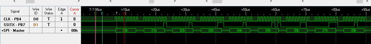
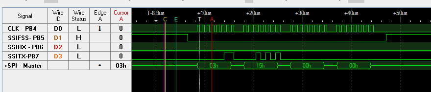
For some reason this is causing a bus error.
//*****************************************************************************
//
// udma_demo.c - uDMA example.
//
// Copyright (c) 2012-2017 Texas Instruments Incorporated.  All rights reserved.
// Software License Agreement
//
// Texas Instruments (TI) is supplying this software for use solely and
// exclusively on TI's microcontroller products. The software is owned by
// TI and/or its suppliers, and is protected under applicable copyright
// laws. You may not combine this software with "viral" open-source
// software in order to form a larger program.
//
// THIS SOFTWARE IS PROVIDED "AS IS" AND WITH ALL FAULTS.
// NO WARRANTIES, WHETHER EXPRESS, IMPLIED OR STATUTORY, INCLUDING, BUT
// NOT LIMITED TO, IMPLIED WARRANTIES OF MERCHANTABILITY AND FITNESS FOR
// A PARTICULAR PURPOSE APPLY TO THIS SOFTWARE. TI SHALL NOT, UNDER ANY
// CIRCUMSTANCES, BE LIABLE FOR SPECIAL, INCIDENTAL, OR CONSEQUENTIAL
// DAMAGES, FOR ANY REASON WHATSOEVER.
//
// This is part of revision 2.1.4.178 of the EK-TM4C123GXL Firmware Package.
//
//*****************************************************************************

#include <stdint.h>
#include <stdbool.h>
#include "inc/hw_ints.h"
#include "inc/hw_memmap.h"
#include "inc/hw_types.h"
#include "inc/hw_uart.h"
#include "inc/hw_ssi.h"
#include "driverlib/fpu.h"
#include "driverlib/gpio.h"
#include "driverlib/interrupt.h"
#include "driverlib/pin_map.h"
#include "driverlib/rom.h"
#include "driverlib/rom_map.h"
#include "driverlib/sysctl.h"
#include "driverlib/systick.h"
#include "driverlib/uart.h"
#include "driverlib/udma.h"
#include "driverlib/ssi.h"
#include "utils/cpu_usage.h"
#include "utils/uartstdio.h"
#include "utils/ustdlib.h"

//*****************************************************************************
//
//! \addtogroup example_list
//! <h1>uDMA (udma_demo)</h1>
//!
//! This example application demonstrates the use of the uDMA controller to
//! transfer data between memory buffers, and to transfer data to and from a
//! UART.  The test runs for 10 seconds before exiting.
//!
//! UART0, connected to the FTDI virtual COM port and running at 115,200,
//! 8-N-1, is used to display messages from this application.
//
//*****************************************************************************

//*****************************************************************************
//
// The number of SysTick ticks per second used for the SysTick interrupt.
//
//*****************************************************************************
#define SYSTICKS_PER_SECOND     100

//*****************************************************************************
//
// The size of the memory transfer source and destination buffers (in words).
//
//*****************************************************************************
#define MEM_BUFFER_SIZE         1024

//*****************************************************************************
//
// The size of the UART transmit and receive buffers.  They do not need to be
// the same size.
//
//*****************************************************************************
#define UART_TXBUF_SIZE         256
#define UART_RXBUF_SIZE         256

//*****************************************************************************
//
// The source and destination buffers used for memory transfers.
//
//*****************************************************************************
static uint32_t g_ui32SrcBuf[MEM_BUFFER_SIZE];
static uint32_t g_ui32DstBuf[MEM_BUFFER_SIZE];


//*****************************************************************************
//
// The count of uDMA errors.  This value is incremented by the uDMA error
// handler.
//
//*****************************************************************************
static uint32_t g_ui32uDMAErrCount = 0;

//*****************************************************************************
//
// The number of seconds elapsed since the start of the program.  This value is
// maintained by the SysTick interrupt handler.
//
//*****************************************************************************
static uint32_t g_ui32Seconds = 0;

//*****************************************************************************
//
// The control table used by the uDMA controller.  This table must be aligned
// to a 1024 byte boundary.
//
//*****************************************************************************
#if defined(ewarm)
#pragma data_alignment=1024
uint8_t ui8ControlTable[1024];
#elif defined(ccs)
#pragma DATA_ALIGN(ui8ControlTable, 1024)
uint8_t ui8ControlTable[1024];
#else
uint8_t ui8ControlTable[1024] __attribute__ ((aligned(1024)));
#endif

//*****************************************************************************
//
// The error routine that is called if the driver library encounters an error.
//
//*****************************************************************************
#ifdef DEBUG
void
__error__(char *pcFilename, uint32_t ui32Line)
{
    while(1)
    {
        //
        // Hang on runtime error.
        //
    }
}
#endif

//*****************************************************************************
//
// The interrupt handler for the SysTick timer.  This handler will increment a
// seconds counter whenever the appropriate number of ticks has occurred.  It
// will also call the CPU usage tick function to find the CPU usage percent.
//
//*****************************************************************************
void
SysTickHandler(void)
{
    static uint32_t ui32TickCount = 0;

    //
    // Increment the tick counter.
    //
    ui32TickCount++;

    //
    // If the number of ticks per second has occurred, then increment the
    // seconds counter.
    //
    if(!(ui32TickCount % SYSTICKS_PER_SECOND))
    {
        g_ui32Seconds++;
    }
}

//*****************************************************************************
//
// The interrupt handler for uDMA errors.  This interrupt will occur if the
// uDMA encounters a bus error while trying to perform a transfer.  This
// handler just increments a counter if an error occurs.
//
//*****************************************************************************
void
uDMAErrorHandler(void)
{
    uint32_t ui32Status;

    //
    // Check for uDMA error bit
    //
    ui32Status = ROM_uDMAErrorStatusGet();

    //
    // If there is a uDMA error, then clear the error and increment
    // the error counter.
    //
    if(ui32Status)
    {
        ROM_uDMAErrorStatusClear();
        g_ui32uDMAErrCount++;
    }
}

//*****************************************************************************
//
// The interrupt handler for uDMA interrupts from the memory channel.  This
// interrupt will increment a counter, and then restart another memory
// transfer.
//
//*****************************************************************************
void
uDMAIntHandler(void)
{
}

#define NUM_SG 4

#pragma DATA_ALIGN(sg_tx_list, 16)
tDMAControlTable
sg_tx_list[NUM_SG] = {
    uDMATaskStructEntry(
        1024,
        UDMA_SIZE_8,
        UDMA_DST_INC_8, &(g_ui32SrcBuf[0]),
        UDMA_DST_INC_NONE, (void*)(SSI2_BASE + SSI_O_DR),
        UDMA_ARB_1,
        UDMA_MODE_BASIC),
};

#pragma DATA_ALIGN(sg_rx_list, 16)
tDMAControlTable
sg_rx_list[NUM_SG] = {
    uDMATaskStructEntry(
        1024,
        UDMA_SIZE_8,
        UDMA_SRC_INC_NONE, (uintptr_t)(SSI2_BASE + SSI_O_DR),
        UDMA_DST_INC_8, &(g_ui32SrcBuf[0]),
        UDMA_ARB_1,
        UDMA_MODE_BASIC),
};


//*****************************************************************************
//
// Initializes the uDMA software channel to perform a memory to memory uDMA
// transfer.
//
//*****************************************************************************
void
DispatchSSITransfer(void)
{

    uint_fast16_t ui16Idx;

    //
    // Fill the source memory buffer with a simple incrementing pattern.
    //
    for(ui16Idx = 0; ui16Idx < MEM_BUFFER_SIZE; ui16Idx++)
    {
        g_ui32SrcBuf[ui16Idx] = ui16Idx;
        g_ui32DstBuf[ui16Idx] = MEM_BUFFER_SIZE - ui16Idx;
    }

    //
    // Enable interrupts from the uDMA software channel.
    //
    ROM_IntEnable(INT_UDMA);

    MAP_SSIDisable(SSI2_BASE);

    MAP_SSIConfigSetExpClk(SSI2_BASE,
                           ROM_SysCtlClockGet(),
                           SSI_FRF_NMW,
                           SSI_MODE_MASTER,
                           ROM_SysCtlClockGet()>>4,
                           8);

    MAP_uDMAChannelDisable(UDMA_CH12_SSI2RX);
    MAP_uDMAChannelDisable(UDMA_CH13_SSI2TX);

    MAP_uDMAChannelAttributeDisable(UDMA_CH12_SSI2RX, UDMA_ATTR_ALL);
    MAP_uDMAChannelAttributeDisable(UDMA_CH13_SSI2TX, UDMA_ATTR_ALL);

    ROM_uDMAChannelScatterGatherSet(
            UDMA_CH12_SSI2RX,
            1, &(sg_rx_list[0]),
            1);

    ROM_uDMAChannelScatterGatherSet(
            UDMA_CH13_SSI2TX,
            1, &(sg_tx_list[0]),
            1);

    MAP_SSIIntDisable(SSI2_BASE, 0xFF);

    //MAP_SSIIntEnable(SSI2_BASE, SSI_DMATX);

    MAP_uDMAChannelAssign(UDMA_CH12_SSI2RX);
    MAP_uDMAChannelAssign(UDMA_CH13_SSI2TX);

    MAP_SSIDMAEnable(SSI2_BASE, SSI_DMA_TX);

    //MAP_IntEnable(INT_SSI2);

    MAP_SSIEnable(SSI2_BASE);

    //MAP_uDMAChannelEnable(UDMA_CH12_SSI2RX);
    MAP_uDMAChannelEnable(UDMA_CH13_SSI2TX);
}

//*****************************************************************************
//
// Configure the UART and its pins.  This must be called before UARTprintf().
//
//*****************************************************************************
void
ConfigureUART(void)
{
    //
    // Enable the GPIO Peripheral used by the UART.
    //
    ROM_SysCtlPeripheralEnable(SYSCTL_PERIPH_GPIOA);

    //
    // Enable UART0
    //
    ROM_SysCtlPeripheralEnable(SYSCTL_PERIPH_UART0);
    ROM_SysCtlPeripheralSleepEnable(SYSCTL_PERIPH_UART0);

    //
    // Configure GPIO Pins for UART mode.
    //
    ROM_GPIOPinConfigure(GPIO_PA0_U0RX);
    ROM_GPIOPinConfigure(GPIO_PA1_U0TX);
    ROM_GPIOPinTypeUART(GPIO_PORTA_BASE, GPIO_PIN_0 | GPIO_PIN_1);

    //
    // Use the internal 16MHz oscillator as the UART clock source.
    //
    UARTClockSourceSet(UART0_BASE, UART_CLOCK_PIOSC);

    //
    // Initialize the UART for console I/O.
    //
    UARTStdioConfig(0, 115200, 16000000);
}

static
void
ConfigureSSI2() {
    MAP_SysCtlPeripheralEnable(SYSCTL_PERIPH_GPIOB);
    MAP_SysCtlPeripheralEnable(SYSCTL_PERIPH_SSI2);
    MAP_SysCtlPeripheralReset(SYSCTL_PERIPH_SSI2);

    MAP_GPIOPinConfigure(GPIO_PB4_SSI2CLK);
    MAP_GPIOPinConfigure(GPIO_PB6_SSI2RX);
    MAP_GPIOPinConfigure(GPIO_PB7_SSI2TX);

    MAP_GPIOPinTypeSSI( GPIO_PORTB_BASE, GPIO_PIN_4 | GPIO_PIN_6 | GPIO_PIN_7);
}


//*****************************************************************************
//
// This example demonstrates how to use the uDMA controller to transfer data
// between memory buffers and to and from a peripheral, in this case a UART.
// The uDMA controller is configured to repeatedly transfer a block of data
// from one memory buffer to another.  It is also set up to repeatedly copy a
// block of data from a buffer to the UART output.  The UART data is looped
// back so the same data is received, and the uDMA controlled is configured to
// continuously receive the UART data using ping-pong buffers.
//
// The processor is put to sleep when it is not doing anything, and this allows
// collection of CPU usage data to see how much CPU is being used while the
// data transfers are ongoing.
//
//*****************************************************************************
int
main(void)
{
    static uint32_t ui32PrevSeconds;
    static uint32_t ui32PrevXferCount;
    static uint32_t ui32PrevUARTCount = 0;
    uint32_t ui32XfersCompleted;
    uint32_t ui32BytesTransferred;

    //
    // Enable lazy stacking for interrupt handlers.  This allows floating-point
    // instructions to be used within interrupt handlers, but at the expense of
    // extra stack usage.
    //
    ROM_FPULazyStackingEnable();

    //
    // Set the clocking to run from the PLL at 50 MHz.
    //
    ROM_SysCtlClockSet(SYSCTL_SYSDIV_4 | SYSCTL_USE_PLL | SYSCTL_OSC_MAIN |
                       SYSCTL_XTAL_16MHZ);

    //
    // Enable peripherals to operate when CPU is in sleep.
    //
    ROM_SysCtlPeripheralClockGating(true);

    //
    // Enable the GPIO port that is used for the on-board LED.
    //
    ROM_SysCtlPeripheralEnable(SYSCTL_PERIPH_GPIOF);

    //
    // Enable the GPIO pins for the LED (PF2).
    //
    ROM_GPIOPinTypeGPIOOutput(GPIO_PORTF_BASE, GPIO_PIN_2);

    //
    // Initialize the UART.
    //
    ConfigureUART();

    UARTprintf("\033[2JuDMA Example\n");

    //
    // Show the clock frequency on the display.
    //
    UARTprintf("Tiva C Series @ %u MHz\n\n", ROM_SysCtlClockGet() / 1000000);

    //
    // Show statistics headings.
    //
    UARTprintf("CPU    Memory     UART       Remaining\n");
    UARTprintf("Usage  Transfers  Transfers  Time\n");

    //
    // Configure SysTick to occur 100 times per second, to use as a time
    // reference.  Enable SysTick to generate interrupts.
    //
    ROM_SysTickPeriodSet(ROM_SysCtlClockGet() / SYSTICKS_PER_SECOND);
    ROM_SysTickIntEnable();
    ROM_SysTickEnable();

    //
    // Initialize the CPU usage measurement routine.
    //
    CPUUsageInit(ROM_SysCtlClockGet(), SYSTICKS_PER_SECOND, 2);

    //
    // Enable the uDMA controller at the system level.  Enable it to continue
    // to run while the processor is in sleep.
    //
    ROM_SysCtlPeripheralEnable(SYSCTL_PERIPH_UDMA);
    ROM_SysCtlPeripheralSleepEnable(SYSCTL_PERIPH_UDMA);

    //
    // Enable the uDMA controller error interrupt.  This interrupt will occur
    // if there is a bus error during a transfer.
    //
    ROM_IntEnable(INT_UDMAERR);

    //
    // Enable the uDMA controller.
    //
    ROM_uDMAEnable();

    //
    // Point at the control table to use for channel control structures.
    //
    ROM_uDMAControlBaseSet(ui8ControlTable);

    ConfigureSSI2();

    //
    // Initialize the uDMA memory to memory transfers.
    //
    DispatchSSITransfer();

    //
    // Loop until the button is pressed.  The processor is put to sleep
    // in this loop so that CPU utilization can be measured.
    //
    while(1)
    {
        __asm("\twfi\n");
    }
}