This thread has been locked.

If you have a related question, please click the "Ask a related question" button in the top right corner. The newly created question will be automatically linked to this question.

TM4C123GH6PM: MPU chip destroyed when power is applied

Part Number: TM4C123GH6PM
Other Parts Discussed in Thread: EK-TM4C123GXL

Hi,

I built a new board with a proven core TM4C123GH6PM design I have used in the past.  I brought it up in a very bare configuration (basically the chip on the board with a couple of bypass caps), applied 3.3v from a bench power supply and the chip died.  It had shorted internally.  I removed the chip, inspected the board again, soldered a new chip on, and got the same instant death of the chip. In both cases I had carefully inspected the board for solder shorts before applying power.

I've done this exact same thing with STM32 parts (chip on board, no bypass caps at all, applied power from bench supply) and all worked great. For the third chip I changed tactics and did what I have typically done in the past.  I soldered and tested the 3.3v voltage regulator part of the board, soldered all caps including the ones for the LDO, soldered the MPU, and when I applied 5v to the regulator, the circuit worked perfectly.  Before applying power, testing with a DVM across the 3.v and ground traces of the unpowered board showed an open circuit.  After power was applied it was a dead short. 

To be clear,  I know why one applies capacitors in a circuit, what their function is, why you should have them, etc.  They're in my circuit.  I've been doing this for almost 40 years, so my actions were a conscious decision based on experience, not because I don't know any better.  I have brought STM parts up with nothing but the chip on a board, hooked it to a bench power supply, and all works great.  After I know it works, I then go in and add all the rest of the parts.  I've never had one die instantly.  I decided to try this with the TI chip and it died instantly.

So, my question is: Has anyone ever seen something like this before, and more importantly, know what the specific cause is?

One difference is that the STM parts don't have an on-chip LDO.  The best guess I have right now is that since I didn't have the .1 uf, 1uf, and 2.2 uf trio of caps bypassing the LDO regulator, that the internal LDO regulator was unstable, put out too high a voltage and killed the chip.  But that's just a guess.  I also didn't have the reset pullup resistor in place, but I don't have a good reason why that would cause the chip to short out.

Any thoughts?  I'd especially love to hear from any TI folks. 

  • I have never heard of anyone doing this before, but the LDO filter capacitors are definitely required. See page 21 of TM4C123 System Design Guidelines.

  • Bob,

    Thanks for the feedback.  I agree that the capacitors are required.  That's why I include them in every design I've made with a TM4C123 part.  However, that document (which I have read more than once in the past), says this about the LDO and capacitors:

    The voltage regulator requires a filter capacitor to operate properly

    Not operating properly is a broad phrase subject to interpretation.  For example, I would expect that without the filter caps, there would be increased ripple on the output.  This would definitely fall under the heading of not operating properly.  What is doesn't say is, "Omitting these capacitors will cause instant death of your $10 chip". 

    But I don't know if omitting them causes instant death or not.  My assumption is that if it did, TI would have mentioned it in large, bolded text.  If omitting these caps does cause instant death, then I would earnestly suggest that TI update the TM4C System Design Guidelines document to add this critical information in a way that underscores its seriousness. 

    I'd also love to know if this is what actually killed my chips.  Since I've already blown $20 in chips trying to get this board up, I'm loath to do more experimenting.  However, I imagine that TI has a few dev boards they could sacrifice in the name of science.  Just unsolder those caps, power it up, and see what happens.  I think this would be very useful information.

    I'm still curious if this is the actual problem or if something else is at work.

  • While I cannot condone trying to operate the part without the LDO filter capacitors, I doubt that is what is destroying the parts. I will do the experiment you suggest, but I am currently backlogged with software questions so I might not get to it until next week. In the meantime, I suggest you double or triple check your layout. Particularly the 3.3V power and GND connections. That is most likely the root cause. If you did not do so, I suggest in the future you use a current limited power supply when bringing up a new board.

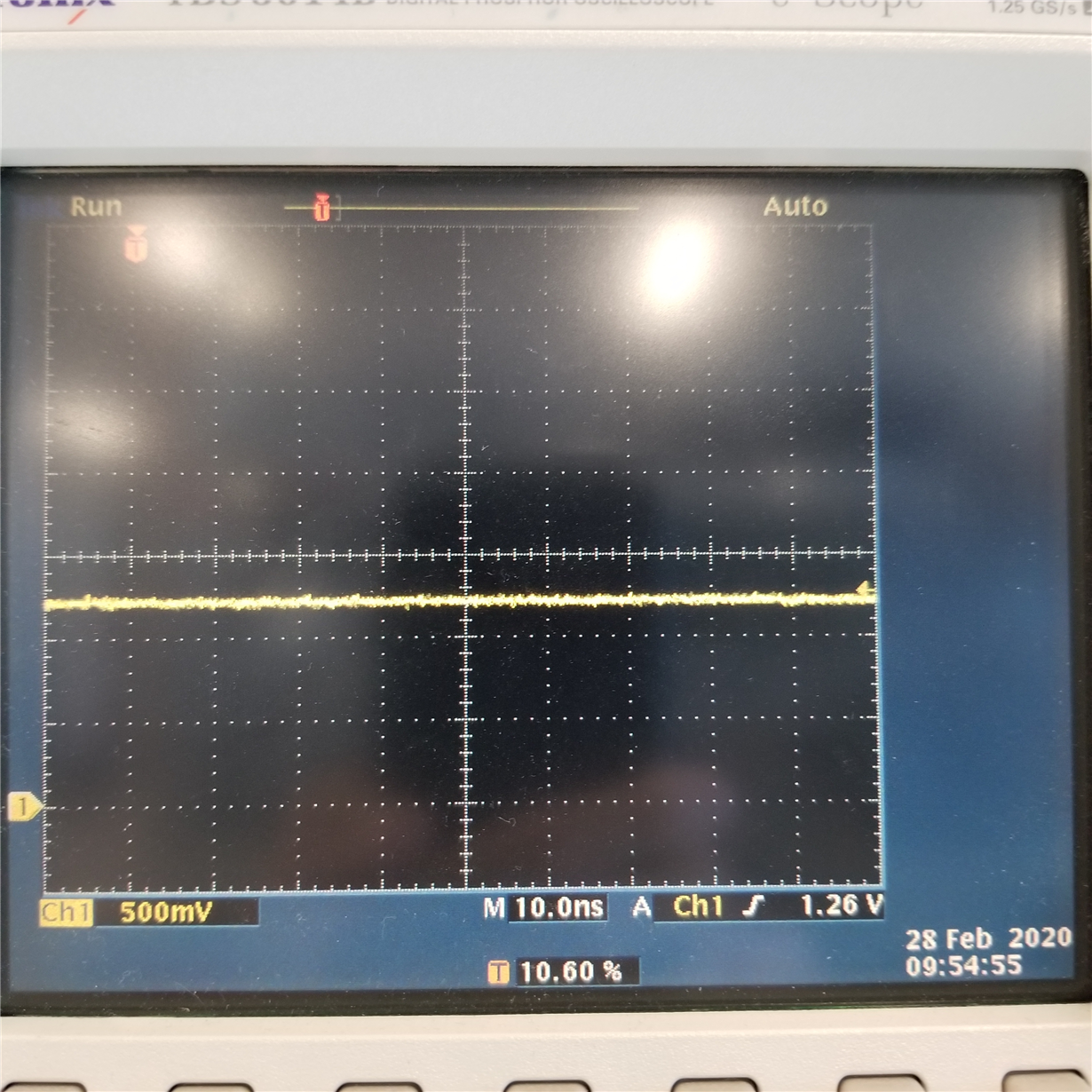
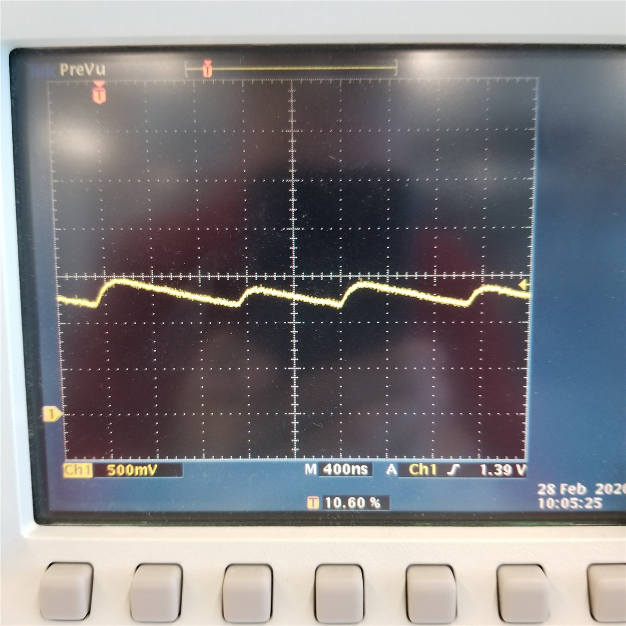
  • As you requested, I took an EK-TM4C123GXL Launchpad and removed the four filter capacitors on the LDO, C10, C11, C12 and C22. The board continued to operate and run code with the capacitors removed, but the core 1.2V showed a sawtooth waveform. Pictures of the core voltage with and without the capacitors is shown below. Bottom line, the part was not damaged.

    Normal with filter caps:

    Without filter capacitors:

  • Greetings Bob,

    Thoughtfully, in advance of promise date - & well done!

    Staff here believed your recommendation of, "Current Limiting the (new) board's powering supply" would, "Go Far to Save the MCU."

    Even a Lab Supply - when powering through the (usual) "banana-style" cables - and then (possible "excess" pcb trace lengths, vias & insufficiently wide routes) may give rise to (unwanted) inductances, "Sufficient to produce Voltage Spikes" which often prove destructive to semi-conductors.

    Note too that the proper: "Value, Number, Location & Distribution of Capacitors" serves to oppose such transient voltage spikes - thus should not be neglected and/or abbreviated!

    While my staff, "Feels this poster's pain" - as a past Tech writer (@ a similar semi-giant) it is "unlikely" that (each/every) potentially damaging situation can be identified & highlighted...   Normal/customary, "Board build practices" provide the best likelihood of a "successful outcome!"

  • Bob,

    I just found the time to login and check this thread.  I really appreciate you taking the time to do the experiment.  A bit bummed that the board continued to work as it still doesn't answer my original question.  I guess at this point the only way for me to suss this out would involved more experiments with my board and $10 chips.  Unfortunately my desire to understand the root cause is overruled by the potential number of $10 chips I'd be throwing away while trying to figure this out.

    Still odd to me that the exact same board with the voltage reg and caps works perfectly, but fries chips when trying to run without those parts and powering via a bench supply.  It shows that my layout is not in question (or else the board would kill chips or otherwise not work with the voltage reg and caps in place), but still leaves me scratching my head.

    Regardless, much appreciation for the time and effort spent on this.  Even though this thread doesn't technically answer my question, I'm still marking it as resolved.  Seems only right.

    Again, thanks for the help!

  • cb1_mobile,

    Agreed.  All of the suggestions make sense, although possible excessive trace lengths and narrows traces is definitely not an issue.  My power traces are 25 mils wide, necking down to 15 and then to 7 just before entry to the chip. 

    I was simply trying to do something I had done before using STM32 parts, and was surprised when the TI parts failed so instantly and permanently. 

    Thanks for taking the time to add to the conversation!