This thread has been locked.

If you have a related question, please click the "Ask a related question" button in the top right corner. The newly created question will be automatically linked to this question.

TM4C123GH6PM: Launchpad TIVA TM4C123G controlling a stepper motor requires a lot of current

Part Number: TM4C123GH6PM

hi,

 I bought a couple of this motor because it was cheap (5 eur) and includes the driver:

https://www.electronicoscaldas.com/datasheet/ULN2003A-PCB.pdf

According to this data sheet the sequence of numbers is 0x3 0x6 0xC 0x9 .

I tried with the most simple  program and connected just one motor to PB3-PB0:

while(1){
GPIO_PORTB_DATA_R =0x33;
SysTick_Wait10ms(2);
GPIO_PORTB_DATA_R =0x66;
SysTick_Wait10ms(2);
GPIO_PORTB_DATA_R =0xCC;
SysTick_Wait10ms(2);
GPIO_PORTB_DATA_R =0x99;
SysTick_Wait10ms(2);
}

It moves but I feel that something is wrong because current consumption is very very high (see the youtube video) and the motor gets a very high temperature

https://youtu.be/EWVaV74dKzs

any idea about the problem?

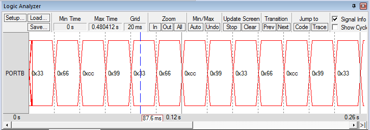
it  seems that TM4C123G output is correct (see keil uVision screen shot)

thanks in advance

Marcos

  • Hello Marcos,

    Our role on E2E is to answer device specific questions for TM4C microcontrollers. Your question unfortunately falls out of scope of this as you have indicated that the TM4C is behaving correctly. We don't know enough about that board you received to offer advice beyond checking your supply voltage and the motor's ratings given that is a point highlighted in the documentation you posted.

    I am not sure what would be a good alternate forum but perhaps you could try https://forum.43oh.com/?

  • is texas providing any driver+stepper motor device? in this case, could I get support?

  • Hello Marcos,

    We do have a TI Design for that: http://www.ti.com/tool/TIDM-TM4C123STEPPERMOTOR

    RE: support, should be okay but support mostly would be for the motor driver as the MCU would already be configured well. If there are configuration questions you can ask them of course, but otherwise questions about the motors would need to go to: https://e2e.ti.com/support/motor-drivers/f/38 

  • Hello,

    Feel your pain - my team is able to offer up several suggestions/guidelines.

    We must note: "I bought a couple of this motor because it was cheap..."    We realize that, "finances may be limited - yet the operation & (especially) life-span of such "discount purchases" often disappoint."    This may be the (entire) cause of your issue...   (untrustworthy and/or (previously damaged/defective) motor (sometimes) are "Sold at such discount.")

    We suggest this course of action:

    • Substitute another motor - does the issue persist?
    • What currents have you measured?    And where & how did you make such measurements?   (we've not the time to "youtube')
    • How are you powering the Stepper Motor Board?   At what voltage?   (Powering (everything) from the (assumed) LPad is almost certain to "cause the issues you note."   An (adequate) power supply (for the Stepper Board) is recommended.
    • At each "step" your code (continues) power for 20mS.    Is that duration required?   If excessive - might that be a 'prime cause' of motor over-heating?
    • We found no 'spec' for the Stepper Motor.   If that's a 5V motor - and driven by the "Darlington ULN2003AN" (as you note) the effective 'Drive Voltage" to the motor is ~ 3.5V.    (Darlington requires low current drive - yet does not pull (fully) to ground!)  We've long used the "ULN200x family" - due to that (reduced) ground level these ICs work best at/above 12V.   (output levels)
    • Should the '123 LPad be 'in play' - your use of PB0 & PB1 (may) require special cautions.   (conflict w/USB - perhaps)   Try another 4 bit port (yet beware of PD0/PD1 & PB6/PB7) which are "joined by Plague-Istors" R9/R10.  (remove/toss those...)

  • hi,

    thanks for your answer.

    • yes, I tried with a different  motor, same model, same consumption.
    • Youtube video is just 12 seconds long. It shows the motor movement , the power source, and the current consumption displayed on power supply: 0.6A a single motor.
    • The power supply is applied to the printed circuit board with the driver, and it says power supply from 5 to 12V. I have used 10V
    • I don't think the problem is with the port. In fact I have adapted a code from John Valvano's MOOC code for a different motor (I was unable to find it, for this reason I chose the other one).

    my impression after reading some more  webs is that this high (according to my criterion) current consumption is "normal", In fact it seems that contrary to common sense, the slower the movements  the higher the consumption. Probably the problem is that I move it very slowly (20ms between each step)

    kind regards

    M.

  • Hi back,

    Thank you - an excellent & prompt response - rare & (very) much appreciated.

    Consider this - "Should an individual Stepper Pulse persist (beyond) that duration required to produce a, "Full-Step?"   And - if that power continues, "Beyond the duration required" - is that not, "Sure to cause heating?"    And likely - in time - to prove destructive?

    Our experience is that several variables will impact the "Minimum Stepper Pulse Duration" required to yield a "Full/Complete/Proper Step!"

    Those variables may include:

    • Present RPM at which the motor is running
    • Motor's Mode: Starting from Stop, Accelerating, Decelerating, (near) Constant Speed, Motor Load, Inertial Effects etc.
    • As such motors are (often) "Micro-Stepped" - the above variables assert even more strongly!    (causing some "Missed" micro-steps!)

    You should be able to experimentally determine the proper duration of your Drive Pulses - and in so doing - the over-heating you note (should) be better managed.   Perhaps SOLVED - thus earning a "REAL Solution" green stamp...

  • hi,

    you mean this?

    while(1){
    GPIO_PORTB_DATA_R =0x33;
    GPIO_PORTB_DATA_R =0x00;
    SysTick_Wait10ms(2);
    GPIO_PORTB_DATA_R =0x66;
    GPIO_PORTB_DATA_R =0x00;
    SysTick_Wait10ms(2);
    GPIO_PORTB_DATA_R =0xCC;
    GPIO_PORTB_DATA_R =0x00;
    SysTick_Wait10ms(2);
    GPIO_PORTB_DATA_R =0x99;
    GPIO_PORTB_DATA_R =0x00;
    SysTick_Wait10ms(2);
    }

    the idea of slow movements was just for visualization purposes. Otherwise it's hard to appreciate the steps

    regards

    nice idea, I will try next week in the lab, and will see what happens

    thanks

  • Hi++;

    Marcos said:
    you mean this?

    GPIO_PORTB_DATA_R =0x33;
    GPIO_PORTB_DATA_R =0x00;
    SysTick_Wait10ms(2);

    Almost!    The 'weakness' of that (quick) code mod. is that you (may) have "over-corrected" the Driving Pulse's duration!   (i.e. the Stepper Drive pulse is likely (now) far too narrow for the Stepper to recognize and/or Accept it...)   BTW - your interface between MCU & Stepper IC is "4-wire" - thus "0x03 or 0x30" should suffice.    (and this enables "4 extra GPIO" for your additional use!)

    As several of our team's most recent posts note - you must "Experimentally Determine" the proper Stepper Drive Pulse Width (duration) and provide that!    Once the Stepper Motor has engaged with its next "Step Position" - continued power (may Not) be Required and (may even) "prove Destructive!"   Depending upon the Stepper Motor - it may be possible to provide a "PWM drive signal" in place of your "20mS duration" signal - which you've noted as causing "over-heating."   (again, experimentation is required to determine the frequency & duty cycle of the PWM)

    The motor document you provided states, "The motor steps when a specific combination of inputs are driven from the microcontroller.  This is just a pulse of power, just enough to get the motor to step."    That's (very much) in agreement w/my team's advice - is it not?   

    Staff, "Ran the numbers" on your motor" (from the spec you provided)

    • Each Full Step causes a, 5.625° rotation of the motor's shaft
    • And there exists a 64:1 gear reduction at the motor's output
    • Thus your (choice) of 20mS per Step will produce, "ONE gear-train Output Revolution" in 82 Seconds!    (& that's believed ... downhill.)

    Should you (instead) operate the motor at more 'normal/customary' speeds - it will be unnecessary to "remove the Stepper Pulse" - you may simply "Cycle from output code to output code" in proper sequence...    May it be asked, "How you arrived at 20mS/Motor Step?"   (in your case - that translates to LESS THAN 1 RPM!)    Note too that a "heated motor" most always will suffer (early) death and "Miss Steps" while (still) operational - yet w/in a "Death Spiral!"

    A (likely improved/solving) code illustration follows:

    GPIO_PORTB_DATA_R =0x33; // Motor Pulse Signal Applied    *** optionally & motor dependent - you may "PWM Drive" each of these 2 outputs - to reduce heating
    SysTick Wait; (tbd) to be determined (duration adequate to insure a "Full Step")
    GPIO PORTB DATA R = 0x00; // Remove Motor Pulse Signal (motor can now COOL!)    *** this step may be eliminated if you drive each motor phase w/a PWM signal
    SysTick Wait; (tbd) this delay (predominantly) yields the Stepper Drive Frequency!
    GPIO PORTB DATA R = (NEXT VALUE); // Next Step Motor Pulse Signal Applied

    Is this not a "REAL SOLUTION" addressing (for the first time) your PRESENT, REAL WORLD, forum-posted ISSUE?    (Green Ink should surely (more properly) now flow...)