This thread has been locked.

If you have a related question, please click the "Ask a related question" button in the top right corner. The newly created question will be automatically linked to this question.

EK-TM4C1294XL: EK-TM4C1294XL with TFT 2.8 SPI Module ILI9341 LCD. Low FPS

Part Number: EK-TM4C1294XL

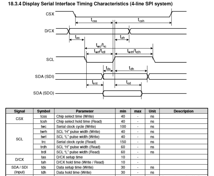
Hi everyone. I'm using EK-TM4C1294XL with TFT 2.8 SPI Module ILI9341 LCD (http://www.lcdwiki.com/2.8inch_SPI_Module_ILI9341_SKU:MSP2807) and i've got a problem: low FPS.

I'm using SYS-BIOS on EK-TM4C1294XL module. I created a little API for easy using SPI

void SPI_Configuration()
{
    SPI_Params_init(&SPI_Parameters);
    SPI_Parameters.mode = SPI_MASTER;
    SPI_Parameters.bitRate = 60000000;
    SPI_Parameters.dataSize = 8;
    SPI_Parameters.transferMode = SPI_MODE_BLOCKING;
    SPI_H = SPI_open(0, &SPI_Parameters);
    if (!SPI_H)
    {
        System_abort("An attempt to configurate module \"SPI\" was unsuccessful!");
    }
}

unsigned char SPI_Send(unsigned char *Data_Ptr, unsigned int Data_Length)
{
    unsigned char Answer = 0x0;
    SPI_Message_Data.count = Data_Length;
    SPI_Message_Data.txBuf = Data_Ptr;
    Answer = SPI_transfer(SPI_H, &SPI_Message_Data);
    return Answer;
}

For LCD i created an API too

void TFT_Send_Command(unsigned char Command)
{
    GPIO_write(TFT_DC, 0);
    SPI_Send(&Command, 1);
}

void TFT_Send_Parameter(unsigned char Parameter)
{
    GPIO_write(TFT_DC, 1);
    SPI_Send(&Parameter, 1);
}

void TFT_Send_Word(unsigned short Word)
{
    GPIO_write(TFT_DC, 1);
    SPI_Send((unsigned char*)&Word, 2);
}

void TFT_Select_Workspace(TFT_Point_Struct Start_Point, TFT_Point_Struct Stop_Point)
{
    TFT_Send_Command(0x2A);
    TFT_Send_Parameter((Start_Point.X & 0xFF00) >> 8);
    TFT_Send_Parameter( Start_Point.X & 0xFF);
    TFT_Send_Parameter(( Stop_Point.X & 0xFF00) >> 8);
    TFT_Send_Parameter(  Stop_Point.X & 0xFF);

    TFT_Send_Command(0x2B);
    TFT_Send_Parameter((Start_Point.Y & 0xFF00) >> 8);
    TFT_Send_Parameter(Start_Point.Y  & 0xFF);
    TFT_Send_Parameter((Stop_Point.Y  & 0xFF00) >> 8);
    TFT_Send_Parameter(Stop_Point.Y   & 0xFF);
}

void TFT_Fill_All_Display(unsigned short Color)
{
    int i = 0;
    TFT_Select_Workspace(TFT_Start_Point, TFT_Stop_Point);
    TFT_Send_Command(0x2C);
    for (i = 0; i < TFT_RESOLUTION_X * TFT_RESOLUTION_Y; i++)
    {
        TFT_Send_Word(Color);
    }
}

void TFT_Turn_On(void)
{
    TFT_Start_Point.X = 0;
    TFT_Start_Point.Y = 0;
    TFT_Stop_Point.X = 240;
    TFT_Stop_Point.Y = 320;
    GPIO_write(TFT_LED_LIGHT, 1);
    GPIO_write(TFT_RESET, 0);
    Task_sleep(150);
    GPIO_write(TFT_RESET, 1);
    Task_sleep(150);
    TFT_Send_Command(0x11);
    Task_sleep(150);
    TFT_Send_Command(0x29);
    Task_sleep(150);

    // Color format
    TFT_Send_Command(0x3A);
    TFT_Send_Parameter(0x55);

    // Gamma 3
    TFT_Send_Command(0xF2);
    TFT_Send_Parameter(0x00);

    // Gamma select
    TFT_Send_Command(0x26);
    TFT_Send_Parameter(0x01);

    // Positive gammga
    TFT_Send_Command(0xE0);
    TFT_Send_Parameter(0x0F);
    TFT_Send_Parameter(0x2A);
    TFT_Send_Parameter(0x28);
    TFT_Send_Parameter(0x08);
    TFT_Send_Parameter(0x0E);
    TFT_Send_Parameter(0x08);
    TFT_Send_Parameter(0x54);
    TFT_Send_Parameter(0xA9);
    TFT_Send_Parameter(0x43);
    TFT_Send_Parameter(0x0A);
    TFT_Send_Parameter(0x0F);
    TFT_Send_Parameter(0x00);
    TFT_Send_Parameter(0x00);
    TFT_Send_Parameter(0x00);
    TFT_Send_Parameter(0x00);

    // Negative gamma
    TFT_Send_Command(0xE1);
    TFT_Send_Parameter(0x00);
    TFT_Send_Parameter(0x15);
    TFT_Send_Parameter(0x17);
    TFT_Send_Parameter(0x07);
    TFT_Send_Parameter(0x11);
    TFT_Send_Parameter(0x06);
    TFT_Send_Parameter(0x2B);
    TFT_Send_Parameter(0x56);
    TFT_Send_Parameter(0x3C);
    TFT_Send_Parameter(0x05);
    TFT_Send_Parameter(0x10);
    TFT_Send_Parameter(0x0F);
    TFT_Send_Parameter(0x3F);
    TFT_Send_Parameter(0x3F);
    TFT_Send_Parameter(0x0F);
}

In main task i'm configurating SPI and LCD and filling it up 1 color in hypercycle

SPI_Configuration();    
TFT_Turn_On();
while (1)
{
    if (i == 0)
    {
        TFT_Fill_All_Display(TFT_GET_COLOR(0, 0, 0));
    }
    else if (i == 1)
    {
        TFT_Fill_All_Display(TFT_GET_COLOR(255, 0, 0));
    }
    else if (i == 2)
    {
        TFT_Fill_All_Display(TFT_GET_COLOR(0, 255, 0));
    }
    else if (i == 3)
    {
        TFT_Fill_All_Display(TFT_GET_COLOR(0, 0, 255));
    }
    i == 3 ? i = 0 : i++;
}

Problem is what LCD is filling up in 1.6 secs. i.e. i've got 0.6 FPS. I don't know what's wrong (But SPI is fine, it's really configurated 60 MHz. I checked this out by my oscilloscope).

Problem exactly in my code because of some guys reached 10+ FPS on this displays on Ard*ino (Proof: https://www.youtube.com/watch?v=WapdjBnF7tQ&t=0s)

I'm stumped with this problem. Please, help me...

  • Greetings,

    May my small group, "Commend you" for your persistence - and willingness to share your development efforts w/others?    While that aspect of your work is good - staff & I are "equally stumped" by your, "Award of Verified" to your (highly) similar, original posting.   (Which was "never" properly resolved ,,, had it been - this follow on thread would not have been required.)

    To your "Slowed Display FILL/Update" - have you considered:

    • identifying the location w/in the code which, "Absorbs MOST of the code's execution time?"
    • then attempting to reduce (ideally eliminate) any functions and/or mechanisms which are not truly "critical?"
    • adopting the TFT's "SPI mode" which best enables the (potential) "Reduction in number of Transmissions" & "other MCU outputs?"
    • properly complying w/the Display's Timing Specifications?    (You are in significant violation - may or may not impact update speed - yet never good!)
    • use of the RTOS - especially when you should strive, "To reduce the number of (potential) delaying and complicating factors in play" is a clear violation of "KISS!"    As earlier noted - initially bypassing the RTOS simplifies & eases your investigation!    And by discovering the performance level achieved "without the RTOS" - you are able to (later) clearly note (any/all) penalties the RTOS is likely (i.e. surely)  to impose...
    • and carefully/critically observing all, "Inter-Character" delays (i.e. between each SPI char. or word transfer) to see "If & How" these may be reduced.

    Let's deal w/each in (the easiest) reverse sequence.    The ILI9341 spec notes:

    Your selection of a "60MHz" SPI clock (SCL) - yielding ~16nS (total pulse width) - grossly undercuts the (40 + 40) 80nS (total) - as spec directed above.    Spec violation is unwise - and while this may "not" be the (entire) cause of your slowed update - it is to be avoided!    (And may indicate a, "Lack of Attention to Detail" - which may lead to (other) spec violations & errant conclusions...)

    SPI Mode: We cannot tell which of the two SPI Modes - offered by the Display - was chosen.   This demands your "configuring" of 4 "IM bits."   We believe that the "4 bit SPI Mode" offered - as shown below - best enables your data transfer via, "16 bits."    Such "wider data transfer" most always increases Update Rate.

    Reduce/Eliminate non critical (yet repetitive) functions: Each/every time through your LOOPING "TFT_Fill_All_Display()" function - it in turn calls, "TFT Send Command()"  causing GPIO_write(TFT_DC, 0); - which may (not) be needed!    (i.e. once the MCU "clears that bit - it remains cleared - does it not?)   (an exception (may) be the "necessity for that bit to toggle." - which presently is unknown...)

    Code which absorbs the bulk of the program's execution time: "TFT_Fill_All_Display()".and that code, "Forces an unnecessary multiplication" (i < TFT_RESOLUTION_X * TFT_RESOLUTION_Y;) to be performed - that (known) result should (instead) be "hard-coded."    More critically,  "TFT_Fill_All_Display()" makes a much repeated function call to,    "TFT_Send_Word(Color)()" - which further delays your Display Transfer!   (In fact - delays the transfer "76,800 individual times" (should you employ 16 bit SPI transfers!)    That code should be moved to w/in "TFT_Fill_All_Display()" - which avoids the "Added program Over-head and associated (massively repeated) delays" - introduced by the (repetitive) function call...

    Note that  "TFT_Fill_All_Display()" employs "TFT_GET_COLOR()" for which we can find "No listing w/in your code!"   

    Due to the sheer VOLUME of SPI Activity - this "Fill_All" code sequence MUST be optimized in the attempt to "speed code execution!"     

  • Hello, cb1_mobile.

    About SPI speed:

    I checked on stm32, raspberry pi and arduino forums SPI speed for this LCD. 60 MHz is good, even if it is not wrote in datasheet.

    About RTOS:

    May be it is slowing. But this LCD i'll use in project there RTOS is required.

    About calculations and function calling in TFT_Fill_All_Display:

    TivaC have 120 MHz. You are really think what this is can slow her? I already checked this function without any extra operations (Like GPIO write and TFT_Send_Word). Results are same.

    P.S. this guy from video i linked in question used Arduino with 16 MHz. So RTOS, exra function calling and GPIO write can't drop down TivaC speed less than Arduino

  • The potential "burden" which the RTOS adds will, "Never be discovered" by your rejection of my suggestion.    I've asked that you eliminate it "initially" - so that its (true) impact may be measured.    Later - armed with that knowledge - you can introduce it.   (And almost certainly "Slow the Screen Update" in that process.)

    Violating vendor specs is NEVER Good!    When operating, "Outside of the spec" unusual, unwanted - even damage may result!

    There are "many" such displays available - some "unofficial!"    Have you a 2nd display - if so - substitute that.    Better still - obtain several from a "different source."

    You offer, "No Support" for your assertion regarding:

    • unnecessary (thus delaying) function calling
    • GPIO writes which (may) be unnecessary
    • inclusion of RTOS - never allowing the vendor's API code to maximize Update Rate

    and you've not revealed several "requested items" - (inter char/word spacing (delay) occurring upon each SPI transaction (which ADD UP) - for one.)

    There exist "More efficient means" to, "Produce 'Real Data' upon this screen" (rather than (only) a repeated color!    Those means demand one who IS properly "coachable."

  • You can tease, I can see that.

    As I said earlier, RTOS can (and most likely does) affect the speed of the LCD, but it's not exactly so strong that I get 0.6 frames per second on a 120 MHz MCU. In any case, I can't refuse to use RTOS, so I have to think about what else might be wrong.

    Calling additional functions is also not considered, because context switching can't slow down the MCU that much.

    About GPIO: the same as with calling additional functions.

    As the basis for my code, I used the Arduino code provided by the developer of LCD:

    //////////////////////////////////////////////////////////////////////////////////	 
    //������ֻ��ѧϰʹ�ã�δ��������ɣ��������������κ���;
    //����Ӳ������Ƭ��STM32F429IGT6,����ԭ��Apollo STM32F4/F7������,��Ƶ180MHZ������12MHZ
    //QDtech-TFTҺ������ for STM32 IOģ��
    //xiao��@ShenZhen QDtech co.,LTD
    //��˾��վ:www.qdtft.com
    //�Ա���վ��http://qdtech.taobao.com
    //wiki������վ��http://www.lcdwiki.com
    //��˾�ṩ����֧�֣��κμ������⻶ӭ��ʱ����ѧϰ
    //�̻�(����) :+86 0755-23594567 
    //�ֻ�:15989313508���빤�� 
    //����:lcdwiki01@gmail.com    support@lcdwiki.com    goodtft@163.com 
    //����֧��QQ:3002773612  3002778157
    //��������QQȺ:324828016
    //��������:2018/08/09
    //�汾��V1.0
    //��Ȩ���У�����ؾ���
    //Copyright(C) ������ȫ�����Ӽ������޹�˾ 2018-2028
    //All rights reserved
    /****************************************************************************************************
    //=========================================��Դ����================================================//
    //     LCDģ��                STM32��Ƭ��
    //      VCC          ��        DC5V/3.3V      //��Դ
    //      GND          ��          GND          //��Դ��
    //=======================================Һ���������߽���==========================================//
    //��ģ��Ĭ��������������ΪSPI����
    //     LCDģ��                STM32��Ƭ��    
    //    SDI(MOSI)      ��          PF9          //Һ����SPI��������д�ź�
    //    SDO(MISO)      ��          PF8          //Һ����SPI�������ݶ��źţ��������Ҫ�������Բ�����
    //=======================================Һ���������߽���==========================================//
    //     LCDģ�� 					      STM32��Ƭ�� 
    //       LED         ��          PD6          //Һ������������źţ��������Ҫ���ƣ���5V��3.3V
    //       SCK         ��          PF7          //Һ����SPI����ʱ���ź�
    //      DC/RS        ��          PD5          //Һ��������/��������ź�
    //       RST         ��          PD12         //Һ������λ�����ź�
    //       CS          ��          PD11         //Һ����Ƭѡ�����ź�
    //=========================================������������=========================================//
    //���ģ�鲻���������ܻ��ߴ��д������ܣ����Dz���Ҫ�������ܣ�����Ҫ���д���������
    //	   LCDģ��                STM32��Ƭ�� 
    //      T_IRQ        ��          PH11         //�����������ж��ź�
    //      T_DO         ��          PG3          //������SPI���߶��ź�
    //      T_DIN        ��          PI3          //������SPI����д�ź�
    //      T_CS         ��          PI8          //������Ƭѡ�����ź�
    //      T_CLK        ��          PH6          //������SPI����ʱ���ź�
    **************************************************************************************************/			
     /* @attention
      *
      * THE PRESENT FIRMWARE WHICH IS FOR GUIDANCE ONLY AIMS AT PROVIDING CUSTOMERS
      * WITH CODING INFORMATION REGARDING THEIR PRODUCTS IN ORDER FOR THEM TO SAVE
      * TIME. AS A RESULT, QD electronic SHALL NOT BE HELD LIABLE FOR ANY
      * DIRECT, INDIRECT OR CONSEQUENTIAL DAMAGES WITH RESPECT TO ANY CLAIMS ARISING
      * FROM THE CONTENT OF SUCH FIRMWARE AND/OR THE USE MADE BY CUSTOMERS OF THE
      * CODING INFORMATION CONTAINED HEREIN IN CONNECTION WITH THEIR PRODUCTS.
    **************************************************************************************************/	
    #include "lcd.h"
    #include "stdlib.h"
    #include "delay.h"	 
    #include "spi.h"
    
    	   
    //����LCD��Ҫ����
    //Ĭ��Ϊ����
    _lcd_dev lcddev;
    
    //������ɫ,������ɫ
    u16 POINT_COLOR = 0x0000,BACK_COLOR = 0xFFFF;  
    u16 DeviceCode;	 
    
    /*****************************************************************************
     * @name       :void LCD_WR_REG(u8 data)
     * @date       :2018-08-09 
     * @function   :Write an 8-bit command to the LCD screen
     * @parameters :data:Command value to be written
     * @retvalue   :None
    ******************************************************************************/
    void LCD_WR_REG(u8 data)
    { 
       LCD_CS_CLR;     
    	 LCD_RS_CLR;	  
       SPIv_WriteData(data);
       LCD_CS_SET;	
    }
    
    /*****************************************************************************
     * @name       :void LCD_WR_DATA(u8 data)
     * @date       :2018-08-09 
     * @function   :Write an 8-bit data to the LCD screen
     * @parameters :data:data value to be written
     * @retvalue   :None
    ******************************************************************************/
    void LCD_WR_DATA(u8 data)
    {
       LCD_CS_CLR;
    	 LCD_RS_SET;
       SPIv_WriteData(data);
       LCD_CS_SET;
    }
    
    /*****************************************************************************
     * @name       :void LCD_WriteReg(u8 LCD_Reg, u16 LCD_RegValue)
     * @date       :2018-08-09 
     * @function   :Write data into registers
     * @parameters :LCD_Reg:Register address
                    LCD_RegValue:Data to be written
     * @retvalue   :None
    ******************************************************************************/
    void LCD_WriteReg(u8 LCD_Reg, u16 LCD_RegValue)
    {	
    	LCD_WR_REG(LCD_Reg);  
    	LCD_WR_DATA(LCD_RegValue);	    		 
    }	   
    
    /*****************************************************************************
     * @name       :void LCD_WriteRAM_Prepare(void)
     * @date       :2018-08-09 
     * @function   :Write GRAM
     * @parameters :None
     * @retvalue   :None
    ******************************************************************************/	 
    void LCD_WriteRAM_Prepare(void)
    {
    	LCD_WR_REG(lcddev.wramcmd);
    }	 
    
    /*****************************************************************************
     * @name       :void Lcd_WriteData_16Bit(u16 Data)
     * @date       :2018-08-09 
     * @function   :Write an 16-bit command to the LCD screen
     * @parameters :Data:Data to be written
     * @retvalue   :None
    ******************************************************************************/	 
    void Lcd_WriteData_16Bit(u16 Data)
    {	
       LCD_CS_CLR;
       LCD_RS_SET;  
       SPIv_WriteData(Data>>8);
    	 SPIv_WriteData(Data);
       LCD_CS_SET;
    }
    
    /*****************************************************************************
     * @name       :void LCD_DrawPoint(u16 x,u16 y)
     * @date       :2018-08-09 
     * @function   :Write a pixel data at a specified location
     * @parameters :x:the x coordinate of the pixel
                    y:the y coordinate of the pixel
     * @retvalue   :None
    ******************************************************************************/	
    void LCD_DrawPoint(u16 x,u16 y)
    {
    	LCD_SetCursor(x,y);//���ù��λ�� 
    	Lcd_WriteData_16Bit(POINT_COLOR); 
    }
    
    /*****************************************************************************
     * @name       :void LCD_Clear(u16 Color)
     * @date       :2018-08-09 
     * @function   :Full screen filled LCD screen
     * @parameters :color:Filled color
     * @retvalue   :None
    ******************************************************************************/	
    void LCD_Clear(u16 Color)
    {
      unsigned int i,m;  
    	LCD_SetWindows(0,0,lcddev.width-1,lcddev.height-1);   
    	LCD_CS_CLR;
    	LCD_RS_SET;
    	for(i=0;i<lcddev.height;i++)
    	{
        for(m=0;m<lcddev.width;m++)
        {	
    			Lcd_WriteData_16Bit(Color);
    		}
    	}
    	 LCD_CS_SET;
    } 
    
    /*****************************************************************************
     * @name       :void LCD_Clear(u16 Color)
     * @date       :2018-08-09 
     * @function   :Initialization LCD screen GPIO
     * @parameters :None
     * @retvalue   :None
    ******************************************************************************/	
    void LCD_GPIOInit(void)
    {
    		GPIO_InitTypeDef GPIO_Initure;
        
        __HAL_RCC_GPIOD_CLK_ENABLE();           //ʹ��GPIODʱ��
    		__HAL_RCC_GPIOF_CLK_ENABLE();           //ʹ��GPIOFʱ��
        
        //PF6
        GPIO_Initure.Pin=GPIO_PIN_5| GPIO_PIN_6|GPIO_PIN_11| GPIO_PIN_12;            //PF6
        GPIO_Initure.Mode=GPIO_MODE_OUTPUT_PP;  //�������
        GPIO_Initure.Pull=GPIO_PULLUP;          //����
        GPIO_Initure.Speed=GPIO_SPEED_HIGH;     //����         
        HAL_GPIO_Init(GPIOD,&GPIO_Initure);     //��ʼ��
    		
    		GPIO_Initure.Pin=GPIO_PIN_7| GPIO_PIN_9;            //PF6
        GPIO_Initure.Mode=GPIO_MODE_OUTPUT_PP;  //�������
        GPIO_Initure.Pull=GPIO_PULLUP;          //����
        GPIO_Initure.Speed=GPIO_SPEED_HIGH;     //����         
        HAL_GPIO_Init(GPIOF,&GPIO_Initure);     //��ʼ��
    		
    		GPIO_Initure.Pin=GPIO_PIN_8;
    		GPIO_Initure.Mode=GPIO_MODE_INPUT;  //�������
    		HAL_GPIO_Init(GPIOF,&GPIO_Initure);     //��ʼ��
    }
    
    /*****************************************************************************
     * @name       :void LCD_RESET(void)
     * @date       :2018-08-09 
     * @function   :Reset LCD screen
     * @parameters :None
     * @retvalue   :None
    ******************************************************************************/	
    void LCD_RESET(void)
    {
    	LCD_RST_CLR;
    	delay_ms(100);	
    	LCD_RST_SET;
    	delay_ms(50);
    }
    
    /*****************************************************************************
     * @name       :void LCD_RESET(void)
     * @date       :2018-08-09 
     * @function   :Initialization LCD screen
     * @parameters :None
     * @retvalue   :None
    ******************************************************************************/	 	 
    void LCD_Init(void)
    {  
    	LCD_GPIOInit();//LCD GPIO��ʼ��	
     	LCD_RESET(); //LCD ��λ
    //*************2.8inch ILI9341��ʼ��**********//	
    	LCD_WR_REG(0xCF);  
    	LCD_WR_DATA(0x00); 
    	LCD_WR_DATA(0xC9); //C1 
    	LCD_WR_DATA(0X30); 
    	LCD_WR_REG(0xED);  
    	LCD_WR_DATA(0x64); 
    	LCD_WR_DATA(0x03); 
    	LCD_WR_DATA(0X12); 
    	LCD_WR_DATA(0X81); 
    	LCD_WR_REG(0xE8);  
    	LCD_WR_DATA(0x85); 
    	LCD_WR_DATA(0x10); 
    	LCD_WR_DATA(0x7A); 
    	LCD_WR_REG(0xCB);  
    	LCD_WR_DATA(0x39); 
    	LCD_WR_DATA(0x2C); 
    	LCD_WR_DATA(0x00); 
    	LCD_WR_DATA(0x34); 
    	LCD_WR_DATA(0x02); 
    	LCD_WR_REG(0xF7);  
    	LCD_WR_DATA(0x20); 
    	LCD_WR_REG(0xEA);  
    	LCD_WR_DATA(0x00); 
    	LCD_WR_DATA(0x00); 
    	LCD_WR_REG(0xC0);    //Power control 
    	LCD_WR_DATA(0x1B);   //VRH[5:0] 
    	LCD_WR_REG(0xC1);    //Power control 
    	LCD_WR_DATA(0x00);   //SAP[2:0];BT[3:0] 01 
    	LCD_WR_REG(0xC5);    //VCM control 
    	LCD_WR_DATA(0x30); 	 //3F
    	LCD_WR_DATA(0x30); 	 //3C
    	LCD_WR_REG(0xC7);    //VCM control2 
    	LCD_WR_DATA(0XB7); 
    	LCD_WR_REG(0x36);    // Memory Access Control 
    	LCD_WR_DATA(0x08); 
    	LCD_WR_REG(0x3A);   
    	LCD_WR_DATA(0x55); 
    	LCD_WR_REG(0xB1);   
    	LCD_WR_DATA(0x00);   
    	LCD_WR_DATA(0x1A); 
    	LCD_WR_REG(0xB6);    // Display Function Control 
    	LCD_WR_DATA(0x0A); 
    	LCD_WR_DATA(0xA2); 
    	LCD_WR_REG(0xF2);    // 3Gamma Function Disable 
    	LCD_WR_DATA(0x00); 
    	LCD_WR_REG(0x26);    //Gamma curve selected 
    	LCD_WR_DATA(0x01); 
    	LCD_WR_REG(0xE0);    //Set Gamma 
    	LCD_WR_DATA(0x0F); 
    	LCD_WR_DATA(0x2A); 
    	LCD_WR_DATA(0x28); 
    	LCD_WR_DATA(0x08); 
    	LCD_WR_DATA(0x0E); 
    	LCD_WR_DATA(0x08); 
    	LCD_WR_DATA(0x54); 
    	LCD_WR_DATA(0XA9); 
    	LCD_WR_DATA(0x43); 
    	LCD_WR_DATA(0x0A); 
    	LCD_WR_DATA(0x0F); 
    	LCD_WR_DATA(0x00); 
    	LCD_WR_DATA(0x00); 
    	LCD_WR_DATA(0x00); 
    	LCD_WR_DATA(0x00); 		 
    	LCD_WR_REG(0XE1);    //Set Gamma 
    	LCD_WR_DATA(0x00); 
    	LCD_WR_DATA(0x15); 
    	LCD_WR_DATA(0x17); 
    	LCD_WR_DATA(0x07); 
    	LCD_WR_DATA(0x11); 
    	LCD_WR_DATA(0x06); 
    	LCD_WR_DATA(0x2B); 
    	LCD_WR_DATA(0x56); 
    	LCD_WR_DATA(0x3C); 
    	LCD_WR_DATA(0x05); 
    	LCD_WR_DATA(0x10); 
    	LCD_WR_DATA(0x0F); 
    	LCD_WR_DATA(0x3F); 
    	LCD_WR_DATA(0x3F); 
    	LCD_WR_DATA(0x0F); 
    	LCD_WR_REG(0x2B); 
    	LCD_WR_DATA(0x00);
    	LCD_WR_DATA(0x00);
    	LCD_WR_DATA(0x01);
    	LCD_WR_DATA(0x3f);
    	LCD_WR_REG(0x2A); 
    	LCD_WR_DATA(0x00);
    	LCD_WR_DATA(0x00);
    	LCD_WR_DATA(0x00);
    	LCD_WR_DATA(0xef);	 
    	LCD_WR_REG(0x11); //Exit Sleep
    	delay_ms(120);
    	LCD_WR_REG(0x29); //display on	
    
      LCD_direction(USE_HORIZONTAL);//����LCD��ʾ����
    	LCD_LED=1;//��������	 
    	LCD_Clear(WHITE);//��ȫ����ɫ
    }
     
    /*****************************************************************************
     * @name       :void LCD_SetWindows(u16 xStar, u16 yStar,u16 xEnd,u16 yEnd)
     * @date       :2018-08-09 
     * @function   :Setting LCD display window
     * @parameters :xStar:the bebinning x coordinate of the LCD display window
    								yStar:the bebinning y coordinate of the LCD display window
    								xEnd:the endning x coordinate of the LCD display window
    								yEnd:the endning y coordinate of the LCD display window
     * @retvalue   :None
    ******************************************************************************/ 
    void LCD_SetWindows(u16 xStar, u16 yStar,u16 xEnd,u16 yEnd)
    {	
    	LCD_WR_REG(lcddev.setxcmd);	
    	LCD_WR_DATA(xStar>>8);
    	LCD_WR_DATA(0x00FF&xStar);		
    	LCD_WR_DATA(xEnd>>8);
    	LCD_WR_DATA(0x00FF&xEnd);
    
    	LCD_WR_REG(lcddev.setycmd);	
    	LCD_WR_DATA(yStar>>8);
    	LCD_WR_DATA(0x00FF&yStar);		
    	LCD_WR_DATA(yEnd>>8);
    	LCD_WR_DATA(0x00FF&yEnd);
    
    	LCD_WriteRAM_Prepare();	//��ʼд��GRAM			
    }   
    
    /*****************************************************************************
     * @name       :void LCD_SetCursor(u16 Xpos, u16 Ypos)
     * @date       :2018-08-09 
     * @function   :Set coordinate value
     * @parameters :Xpos:the  x coordinate of the pixel
    								Ypos:the  y coordinate of the pixel
     * @retvalue   :None
    ******************************************************************************/ 
    void LCD_SetCursor(u16 Xpos, u16 Ypos)
    {	  	    			
    	LCD_SetWindows(Xpos,Ypos,Xpos,Ypos);	
    } 
    
    /*****************************************************************************
     * @name       :void LCD_direction(u8 direction)
     * @date       :2018-08-09 
     * @function   :Setting the display direction of LCD screen
     * @parameters :direction:0-0 degree
                              1-90 degree
    													2-180 degree
    													3-270 degree
     * @retvalue   :None
    ******************************************************************************/ 
    void LCD_direction(u8 direction)
    { 
    			lcddev.setxcmd=0x2A;
    			lcddev.setycmd=0x2B;
    			lcddev.wramcmd=0x2C;
    	switch(direction){		  
    		case 0:						 	 		
    			lcddev.width=LCD_W;
    			lcddev.height=LCD_H;		
    			LCD_WriteReg(0x36,(1<<3)|(0<<6)|(0<<7));//BGR==1,MY==0,MX==0,MV==0
    		break;
    		case 1:
    			lcddev.width=LCD_H;
    			lcddev.height=LCD_W;
    			LCD_WriteReg(0x36,(1<<3)|(0<<7)|(1<<6)|(1<<5));//BGR==1,MY==1,MX==0,MV==1
    		break;
    		case 2:						 	 		
    			lcddev.width=LCD_W;
    			lcddev.height=LCD_H;	
    			LCD_WriteReg(0x36,(1<<3)|(1<<6)|(1<<7));//BGR==1,MY==0,MX==0,MV==0
    		break;
    		case 3:
    			lcddev.width=LCD_H;
    			lcddev.height=LCD_W;
    			LCD_WriteReg(0x36,(1<<3)|(1<<7)|(1<<5));//BGR==1,MY==1,MX==0,MV==1
    		break;	
    		default:break;
    	}		
    }	 
    

    I guess, what problem is in my SPI configuration or send function. May be, i should try to transfer data with 15 uSec timeout with SPI transfer mode Callback

  • There was (and is) "No teasing" - just a series of facts - each offered up in the attempt to, "Be of value to you."

    You are of course, "Free to reject them" ... and allow your (beyond S L O W) Screen Updates to continue...

  • Nah, I'm close to a solution. Now i'm sending 512 bytes in 1 SPI transaction. Now i've got ~5 FPS. I guess i have 1 way: increase bytes count in 1 SPI transaction. I should use DMA or increase SPI TX buffer size (now it's 512 bytes). May be you know how to do this?

  • Hi Georgy,

    Did you achieve this by increasing the SPI dataSize? The maximum data size is 16 bits. The SPI driver for this device already uses the DMA. As pointed out before, you are violating the vendor spec of the lcd and expected behavior is not guaranteed.

    Jaskaran

  • No, i increase bytes in SPI transaction. In my function SPI_Send arg Data_Length was 2. Now it's 512 i.e i'm sending 512 bytes in 1 SPI transaction

  • Jaskaran, you said interesting thing... SPI already uses the DMA? Your colleague disagree...
    https://e2e.ti.com/support/microcontrollers/other/f/908/t/887155

  • Georgy, sorry for that. The SPI driver for the TM4C1294 does use the DMA. The post that Charles is referring to actually says SPI Quad mode is not supported but it still uses the DMA. I will have the post corrected.  Did you try increasing the SPI dataSize?

  • Jaskaran, you mean that string?

    SPI_Parameters.dataSize = 8;

    Yes, i did. If i'll set dataSize 16, for example, LCD will not work

  • Jaskaran, i did it. Now i have (idk, 40, may be?) FPS. Problem solved after changing a number of bytes in 1 SPI transaction and setting SPI speed on 60 MHz. But the 1 question is not answered. How to increase SPI TX buffer size (now it's 512 bytes, as i sad before)?

  • You would need to edit the "SPI_Message_Data.count" that gets set in your SPI_Send function. It can be set to a maximum of 1024 data frames where each data frame is 8 bit or 16 bits depending on what "SPI_Parameters.dataSize" is set to.

  • Yea, i already changed it. For dataSize 8 bit <count> is 512 maximum. If i'm setting up <count> to 513 or higher SPI crushes.

    The question is how to change this 512 value to 513 or higher without crushing SPI?

  • Can you provide more info on what happens when SPI crushes. Does the LCD not respond or does the launchpad stop transmitting?

  • Not that anyone cares here - yet the "Screen Update Speed has improved" due to the, "Reduction in "Inter-Character Delays" - which is achieved by "Increasing the Number of Bytes (or Words) w/in each SPI Transaction."    Such could have been "Far more quickly/easily noted" had the (much earlier) suggestion been followed...   As the MCU's SPI clock rate has continued (unchanged) it is "only" that the reduction in (unwanted) Delay Duration (i.e. "Inter-Character Delay") has occurred!    (that delay is imposed 76,800 times - thus the "Improvement Potential" may prove "massive!")    And was (easily) predicted...

    cb1_mobile said:
    and carefully/critically observing all, "Inter-Character" delays (i.e. between each SPI char. or word transfer) to see "If & How" these may be reduced.

    Above found w/in the post of 8 Mar @ 22:50 - 6th Bullet Point w/in the (detailed) list.   And again - so seriously Violating the Device's  (SCL) Spec - opens the door WIDE to "Future & On-Going HORRORS!"   (which will arise "long after" the Spec Violation has been forgotten...)

    Review of the ILI9341 manual appears, "Not to support" the 16 bit, Serial (SPI) Transaction.

    As noted (several times now) some attention to (and compliance with) the "Targeted Device's Data-Sheet" (and spec) IS required!

  • cb1_mobile,

    if you know how to reduce Inter-Character delays, tell me, please. I'm all ears

  • Has that point not (already) been made clear?    Increasing the number of SPI Transactions w/in the SPI Data Frame has the "welcomed" side effect - of substantially reducing "Inter-Character" AND (likely) other SPI Format Delays...   

    Had you scoped the SPI Transactions - "keying upon any/all (Inter-Character (or other) delays (spacings)" - this would have notably revealed...

    You may benefit by noting that, "Sending (only) a single color to the Display" is vastly different (far easier) than when you are tasked to (both) process, fetch, & present "REAL" (meaningful) Data to the Display!   It is during this far more "Real & demanding effort" - that your program's "weaknesses" will (unhappily) reveal...   (And necessarily - drive down your Update Rate...)

    Shown below is a "Blood Oximeter" - produced by a past firm I co-founded - and which saved literally, "Thousands of Lives!"   The U.S. "FDA" has extremely strict Tech. "Rules & Regulations" - and (Never) did my group: Violate Technical Specifications and/or accept "Tech Guidance" from (random) "youtubers!"    The LCD shown had demanding "Update Rates" - and many of the techniques I "Shared w/you" - enabled the significant success this medical device enjoyed...

    You & others - adopting the more "Methodical & Systematic Techniques" we've presented - may in time realize (similar) rewards...   (both life-saving & financial...)

  • You probably don't understand at all that to do something complicated, you need to start with something simple? Simple-color output, complex - output of useful data. To output useful data, I must first achieve normal FPS, which I do by sending a single color.

    The fact that you saved a lot of lives with your device is great, my respect, but it's not nice to tease a person about the issues they face, at least.

    You can't make 4 bits for SPI because the LCD doesn't have this option.

    Regarding reducing inter-character delays. I reduced them. The question is whether it is possible to reduce the pauses between transactions (They are 23 uSec).It was not possible to reduce them by optimizing the code (I changed the rendering function for the test and do not call unnecessary operations as you said)

  • Georgy, could you please provide more information on what happens when "SPI crushes" when you increase the dataCount past 512? Does the LCD stop responding or does the launchpad stop transmitting.

  • I'm sorry, not 512 bytes. 513 words i.e. 1026 bytes. If i set 1027 bytes SPI it just don't send any data at all. Only noise each ~1 ms 

  • Georgy, this is expected because the dma controller on the device can only support data transfers up to 1024 data frames.According to the datasheet, the LCD can only handle an 8-bit data size so this is the max you can get from our device without increasing the data size.

  • Got it. But can I somehow reduce the pause between SPI transactions? At the moment it is 23 uSec

  • My only thoughts are

    1. Are you compiling your application for speed optimization? That might help a bit.

    2. You can write your own SPI driver and make it a zero-latency interrupt. The kernel will add no latency. .

    Todd

  • Thank you for your advice. In General, I did the following:

    1) Set SPI to Callback mode

    2) Created 2 buffers of 1024 bytes

    3) While I was sending one buffer (Its sending time was about 200 microseconds. Checked with an oscilloscope), I was busy filling in another buffer

    And... It didn't help me. When i'm sending 2 bytes in one SPI transaction, delay is about 23 uSec. When i'm sending 1024 bytes in one SPI transaction, delay is about 600 uSec. I don't know what's the problem. May be i should really try to rewrite SPI driver....

  • Thanks Todd

    The problem is solved. All i need to do is just set optimization to 1-th level and set speed to 5 lvl. Now i have 24 fps.