This thread has been locked.

If you have a related question, please click the "Ask a related question" button in the top right corner. The newly created question will be automatically linked to this question.

EK-TM4C123GXL: capture pwm with timer0A

Part Number: EK-TM4C123GXL
Other Parts Discussed in Thread: EK-TM4C1294XL, TM4C1294NCPDT

Hello,

here is my code to configure timer0A as a capture compare PWM it works with only 16 bit operating modes, I just want to configure it with 32 bit operating mode:

void    init_timer(void)
{
        // Enable and configure Timer0 peripheral.
        SysCtlPeripheralEnable(SYSCTL_PERIPH_TIMER0);

        // Initialize timer A and B to count up in edge time mode
        TimerConfigure(TIMER0_BASE, (TIMER_CFG_SPLIT_PAIR | TIMER_CFG_A_CAP_TIME));//when i'm trying to change TIMER_CFG_SPLIT_PAIR it doesn't work

        // Timer a records pos edge time
        TimerControlEvent(TIMER0_BASE, TIMER_A, TIMER_EVENT_POS_EDGE);

        //configure timer to count all its width
        TimerLoadSet(TIMER0_BASE, TIMER_A, 0xFFFF);//so when i putting(0xFFFFFFFF)it just loads (0xFFFF) 

        //Configure the pin that the timer reads from (PB6)
        SysCtlPeripheralEnable(SYSCTL_PERIPH_GPIOB);
        GPIOPinConfigure(GPIO_PB6_T0CCP0);
        GPIOPinTypeTimer(GPIO_PORTB_BASE, GPIO_PIN_6);

        // Registers a interrupt function to be called when timer b hits a neg edge event
        IntRegister(INT_TIMER0A, ISR_Capture);//ISR_Capture is my ISR code 

        // Makes sure the interrupt is cleared
        TimerIntClear(TIMER0_BASE, TIMER_CAPA_EVENT);

        // Enable the indicated timer interrupt source.
        TimerIntEnable(TIMER0_BASE, TIMER_CAPA_EVENT);

        // The specified interrupt is enabled in the interrupt controller.
        IntEnable(INT_TIMER0A);
}

So, what should i do or change to make the timer works with 32 bit as a capture compare unit? 

  • I've found the problem. I haven't noticed that there is a wide timers that have extended registers up to 64. If anyone has the same problem, you just have to do simple changes to use the wide timers. the code will be:

    void    init_timer(void)
    {
            // Enable and configure Timer0 peripheral.
            SysCtlPeripheralEnable(SYSCTL_PERIPH_WTIMER0);
    
            // Initialize timer A to count down in edge time mode
            TimerConfigure(WTIMER0_BASE, (TIMER_CFG_SPLIT_PAIR | TIMER_CFG_A_CAP_TIME));
    
            // Timer a records pos edge 
            TimerControlEvent(WTIMER0_BASE, TIMER_A, TIMER_EVENT_POS_EDGE);
    
            TimerLoadSet64(WTIMER0_BASE ,0xffffffff); //i've put the max value so i can measure the slow pulses. 
            
            //Configure the pin that the timer reads from (PC4) which is WT0CCP0
            SysCtlPeripheralEnable(SYSCTL_PERIPH_GPIOC);
            GPIOPinConfigure(GPIO_PC4_WT0CCP0);
            GPIOPinTypeTimer(GPIO_PORTC_BASE, GPIO_PIN_4);
    
            // Registers a interrupt function to be called when timerA hits a Pos edge event
            IntRegister(INT_WTIMER0A, ISR_Capture);
    
            // Makes sure the interrupt is cleared
            TimerIntClear(WTIMER0_BASE, TIMER_CAPA_EVENT);
            // Enable the indicated timer interrupt source.
            TimerIntEnable(WTIMER0_BASE, TIMER_CAPA_EVENT);
            // The specified interrupt is enabled in the interrupt controller.
            IntEnable(INT_WTIMER0A);
    }
    
    float ms;
    void ISR_Capture(void)
    {
        static uint8_t Count= 0 ;
        static uint32_t Start= 0;
        static uint32_t End= 0;
    
        TimerIntClear(WTIMER0_BASE, TIMER_CAPA_EVENT);
        if      (Count==0)//coming raising edge
        {
                Start= TimerValueGet(WTIMER0_BASE, TIMER_A);
                TimerControlEvent(WTIMER0_BASE, TIMER_A, TIMER_EVENT_NEG_EDGE);//the next time capture falling edge
                Count= 1;
                return;
        }
    
        if      (Count==1)//coming falling edge
        {
                End= TimerValueGet(WTIMER0_BASE, TIMER_A);//the next time capture raising edge
                TimerControlEvent(WTIMER0_BASE, TIMER_A, TIMER_EVENT_POS_EDGE);
                if      (End <Start)        {   ms= (Start - End)/80;   }//convert to micro seconds
                else    {   ms= (TimerLoadGet((WTIMER0_BASE), TIMER_A)- End + Start)/80;    }
                Count= 0;
        }
    
    }
  • Hello Mo,

    Glad to hear you were able to figure it out pretty quickly, sorry we couldn't help sooner but we are all US based. :) Appreciate you sharing your adjustment with the community, hopefully others can reference your post!

  • Greetings,

    While my small tech group is generally pleased w/your (kind) "PWM Measure" presentation may we ask for clarification:

    • the "80" w/in your code suggests that the TM4C123 employs a system clock set to 80MHz - might you confirm?
    • which variable - if any - identifies the "Duty Cycle?"    (that's normally the objective of PWM Measure)
    • Timer_A must transition between "Timer_Event_Pos_Edge" and then "Timer_Event_Neg_Edge."   This "single timer" restriction enforces a measurement limitation upon (both) "Maximum & Minimum Duty Cycle Measurements - does it not?    Might you supply the limitations which the single timer usage imposes?
    • Had you considered "expanding the code" so that a, "Sequence of PWM Measurements (perhaps 4 or 8 in succession (total)) - rather than "just one" is achieved & reported?"   This proves desirable as "single PWM Measures"are "less forgiving" & notably more vulnerable to (noise/other) measurement errors! 
    • It should prove (almost) "Free" to include "Frequency Measurement" as well - raising the value & usefulness of your good work...

    While beyond the scope of this post - the addition of a character LCD & minimal keypad - enable the creation of an MCU-based, "Stand-Alone product." 
    Ideally one w/expanded capability to include:

    • frequency measurement, setting & generation
    • both PWM input (measure) & output (generation) - keypad/display set/controlled/viewed
    • Following the PWM output w/a proper "R-C network" enables the creation of a "DAC" (long missing from this "other" MCU series)
    • Measurement & Display of "Multiple Analog Voltages" (beyond any DMM's capability) - via one compact, battery powered instrument.   (eliminates "endless" Scope/DMM 'Connect/Remove/Re-Connect' time/effort & 'circuit damage' potential!)

    Tag: "Bigger, more imaginative Dreams offer expanded value & benefits..."

  • Hello Ralph,

    Thanks for your kind. You are always here to help and i appreciate that.

    Best regards. 

  • Hello Cb1_mobile,

    First things first this is a simple version of code to just compute the time of the duty cycle to any signal. I wanted to use it to interface HC-SR04 sensor to just compute the time of the echo signal to just measure the distance. So this code doesn't compute the frequency, only the duty cycle time.

    1- The system clock is 80 MHZ.

    2 - The variable "ms" is used to hold the time of duty cycles in micro seconds. 

    3 - The maximum duty cycle time i wanted to get was 7 ms so i just put the maximum count to just test the first version of the code. In the second version the  timer interrupt will be smaller and at this case i will use a counter to count the number of overflows. I wanted to compute the duty cycle with just one timer channel so as you see the timer must transforms from RAISING edge detector to FALLING edge detector at every time.

    4- Maybe i will consider  "expanding the code" in the next version. Thanks for your advice.

    Thanks for you interest and hope this message finds you well.

  • Greetings,

    As earlier stated - your kindness in presenting your solution was (and remains) appreciated.

    Our group agrees that in your application (HC-SR04) the duration of the pulse signal proves sufficient.    Yet - PWM more normally/customarily includes "Duty Cycle" - which as you know is calculated by:  T_high/(T_high + T_low)  where "T_high & T_low" represent the signal's timed duration during each logic state.   Usually this Duty Cycle is presented as a percentage - which increases when T_high dominates the PWM period.

    Accuracy is improved by measuring over multiple PWM periods - such may add to the usefulness of your example.

    And - any use of "Just a single Timer" raises code complexity & (at extreme) duty cycles and/or frequencies - introduces error due to the "transitioning between signal edges."   As ARM MCUs employ many timers - single timer usage imposes a cost.

    Prior to forum readers adopting your "PWM Measure" solution - they must insure that the "external PWM signal they introduce" remains fully w/in the MCU's input pin specifications.   (series resistor followed by a Schottky diode to Vdd offers (some) protection - yet simple "Awareness" comes first!)

    We suggested the, "Addition of (both) Char. Lcd & keypad" (i.e. Productionizing your idea) - as (many) would find such a compact device of repeated use & value!    (especially so if expanded to present frequency & multi-channel analog voltage display.)

    Staff (almost) never suggests, "Something they themselves (could not or would not) design or execute!"     Revealed is a 2x8 Lcd w/"5-Way Navigation Switch" (N,S,E,W & In)   This met client demand for "smallest Operator Interface" - messages beyond 8 char. width simply "scrolled across the screen" - over 5K such devices were produced...

  • Mo said:
    I haven't noticed that there is a wide timers that have extended registers up to 64.

    Hi Mo,

    Are you certain the 123g class device supports 64 bit wide split pair timers?

    Feeling somewhat cheated since TM4C1294 "a vastly superior MCU" only incorporates 32 bit wide GPTM timers. Wonder why TI elected not to install 64 bit timers into the TM4C1294 class devices or discuss them in datasheet if they indeed exist. Perhaps a step backwards as newer device classes added to a family tree tend to improve silicon designs along the way. Addition of Prescale register adds another 8 bits 24 total does not make it 64 bit wide. Rather 24 bits for most purposed capture functions splitting 32 bit wide into 16 bit wide A0/A1 with prescale ability

    Though Fig.13-1 states 64 bit wide there is no datasheet text to further TM4C diagram in any way has 64 bit wide timer modes.

    How could the TM4C123g have 64 bit wide timers and the TM4C1294 not, has the community been bamboozled?

  • It would seem the TM4C123g has similar split wide restrictions TM4C1294 though datasheet sales pitch states 32/64 CCP. It would seem 123g has only 32 bit CCP when prescale added to split pair. And GPTM-TAILR / TBILR registers notes do not say 32 bits are indeed used for split pair, perhaps a 64 bit wide timer non split timer can. Seemingly 123g only gains 16 bits with prescale 32 bit split mode, not 64 as datasheet sales pitch eludes one to believe.

    When a 16/32-bit GPTM is configured to one of the 32-bit modes, GPTMTAILR appears as a 32-bit register (the upper 16-bits correspond to the contents of the GPTM Timer B Interval Load (GPTMTBILR) register). In a 16-bit mode, the upper 16 bits of this register read as 0s and have no effect on the state of GPTMTBILR.

    When a 32/64-bit Wide GPTM is configured to one of the 64-bit modes, GPTMTAILR contains bits 31:0 of the 64-bit count and the GPTM Timer B Interval Load (GPTMTBILR) register contains bits 63:32.

  • So 123g only gains 8 bits for 32 bit wide split CCPn timer and 16 bits for nonsplit 64 wide timer. That is nice feature the TM4C1294 shoved aside as if would never be required. Point is you have a 32 bit split wide configuration in your above code only gain 8 bits for match count interrupts.

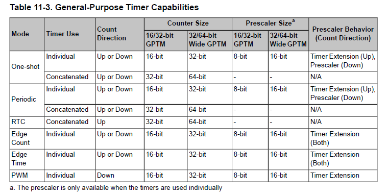
    So the load call TimerLoadSet64(WTIMER0_BASE ,0xffffffff); is being truncated at  8 bits according to table 11-3. 

  • Hello Gl,

    This application isn't using Periodic or One-Shot mode, so it is only 32-bit wide and therefore the TimerLoadSet64(WTIMER0_BASE ,0xffffffff); works as intended.

    Also keep track of the Counter Size vs Prescaler size on Table 11-3. I think your misunderstanding on the amount of bits gained comes from there.

    Also, please keep the topic on the technical issues here. If you have serious concerns regarding the feature sets then we can address that in a dedicated thread that does not pollute technical discussion, thank you.

  • Ralph Jacobi said:
    This application isn't using Periodic or One-Shot mode, so it is only 32-bit wide and therefore the TimerLoadSet64(WTIMER0_BASE ,0xffffffff); works as intended.

    Right for full 64 bit wide timer as table 11-3 indicates 64 bits are possible but not for 16 bit split mode, the prescale resister is not 32 bits wide as you are saying.

    Ralph Jacobi said:
    Also, please keep the topic on the technical issues here.

    Please keep in mind this forum is open to all pubic discussions relative to TI MCU family Other. 

  • Hello Gl,

    Gl said:
    Right for full 64 bit wide timer as table 11-3 indicates 64 bits are possible but not for 16 bit split mode, the prescale resister is not 32 bits wide as you are saying.

    TimerLoadSet and TimerLoadSet64 are not for the prescaler. TimerPrescaleSet is for the prescaler.

    Which by the way, Mo is not using in his application.

    TimerLoadSet64(WTIMER0_BASE ,0xffffffff); is a valid call for Mo's application and it is loading all 32-bits.

    Gl said:
    Please keep in mind this forum is open to all pubic discussions relative to TI MCU family Other. 

    Yes the forum is open but this is a thread which Mo has opened and the conversation he has brought up is on technical issues. New posts can be made to discuss other topics.

  • Ralph Jacobi said:
    TimerLoadSet64(WTIMER0_BASE ,0xffffffff); is a valid call for Mo's application and it is loading all 32-bits.

    I first stated prescale since TM4C1294 must use for load counts >24 bits. Yet Mo's load value exceeds 32 bits for 16/32 bit split pair timer was more the point. The 32 bit load value will be truncated according to Table 11-3 less the timer is 32 wide, AKA non-split pair. Thus prescale register must be used for load values >16 bits with Tivaware configuration above code snip. My posted snips above are from the 123g datasheet not 1294. 

    Ralph Jacobi said:
    Yes the forum is open but this is a thread which Mo has opened and the conversation he has brought up is on technical issues. New posts can be made to discuss other topics.

    My reply was to MO not Ralph and was relative to GPTM devices in any MCU class.

    Agree a technical issue and TI should keep consistent peripherals in the same device classes to make support more focused. The EK-TM4C1294XL has 123g IDCI MCU and made it appear to be lessor product yet it has 144 pins on other MUC's. When we learn via forum posts device class peripherals all over the road it makes one very nervous to see that kind of driving no matter who is behind the wheel. 

  • Gl said:
    The 32 bit load value will be truncated according to Table 11-3 less the timer is 32 wide, AKA non-split pair. 

    And that is what WTIMER0_BASE is doing? What you are describing is exactly what Mo faced and solved.

    Post #1, used TIMER0_BASE for Split Timer, saw 16 bit loading.

    Post #2, fixed by using WTIMER0_BASE for wide timer, saw 32 bit loading.

    We are just re-hashing an already solved point.

  • Ralph Jacobi said:
    Post #2, fixed by using WTIMER0_BASE for wide timer, saw 32 bit loading.

    Ok I see your point and only the first posted snip was showing for reference. It brought up a valid point 16/32 bit 1294 GPTM figure 13-1 shows similar 64 bit Up/Dn counts but do not exist in datasheet CTRL registers. That confuses since Table 11-3 123g datasheet shows both 16/32 and 32/64 bit GPTM and Tivaware configures both MCU classes. Seemingly both are Snowflake related brothers can use the same driverlib calls. 

    Reason to question does 1294 GPTM actually support 64 bit Up/Dn counts showing in Fig.13-1. Would be nice if the Tivaware 64 bit load count call can work for 129 same as it does 123g. 

  • Hello Gl,

    Gl said:
    Reason to question does 1294 GPTM actually support 64 bit Up/Dn counts showing in Fig.13-1.

    Check Table 13-3. General-Purpose Timer Capabilities of the datasheet for TM4C1294NCPDT. No mention of 64 bit count anywhere, so no it doesn't support that.

  • TM4C1294 Fig.13-1 comes way before Table 13-3 so 32/64 bit Up/Dn counts note must be a misprint. Again today green resolved post code snip is showing TIMER_CFG_SPLIT_PAIR configured. Seemingly the resolved post was edited, today Chrome history is showing the original before yesterday edit to TIMER_CFG_WIDE. Table 11-3 headers would seem to indicate 123g GPTM must be configured WIDE, not SPLIT as to assert 32 bit loads in contrast to TM4C1294 16/32 GPTM shown in same Table 11-3.

    So the 123g 64 bit GPTM can be configured split pair for loading 32 bit counts but 1294 is restricted to 16 bits for same split pair via Tivaware? Otherwise 1294 split pair 32 bit load value will be truncated to 16 bits per table 11-3. That seems to have even confused 1294 datasheet writers Fig.13-1. We want the 16 bits back taken from 1294 spit pair - lol

  • Hello Gl,

    Okay I see what you are saying with Figure 13-1. Yes the 32/64 notes are not correct. Presumably the documentation structure from 123x was used to make the same block for 129x D/S and that was not updated right.

    Regarding TIMER_CFG_SPLIT_PAIR, Mo is using 32 bits with just one timer. Not 64 with both. So he is using TIMER_CFG_SPLIT_PAIR with WTIMER0_BASE. You can do both Wide and Split, which gets you two 32 bit Timers.

    Also there is no TIMER_CFG_WIDE - where did you even get that from? Search TivaWare, it doesn't exist, not does anything similiar.

    Gl said:
    So the 123g 64 bit GPTM can be configured split pair for loading 32 bit counts but 1294 is restricted to 16 bits for same split pair via Tivaware?

    It's not restricted via TivaWare. The hardware supports two 16 bit timers as split pair, each with an 8 bit pre-scaler to make them effectively 24 bit timers, or one 32 bit timer when concatenated. Again, Figure 13-1 should not mention the 32/64 bits, but human error. If such a feature existed it would have been mentioned in more than just a footnote within a single block diagram.

  • Ralph Jacobi said:
    Mo is using 32 bits with just one timer. Not 64 with both. So he is using TIMER_CFG_SPLIT_PAIR with WTIMER0_BASE. You can do both Wide and Split, which gets you two 32 bit Timers.

    Yea I kept searching for where all the TM4C1294  64 bit wide timers got off to. It would be really nice if they were indeed 64 bit wide for 32 bit split reasons.

    Some how managed to make 8 timers barely do the job and did not depend on default 32 bit timeout re-load 0xFFFF.FFFF for OneShot/Periodic modes. Instead configured GPTM for match count re-load value 0x1 to increase the interrupt count down precision. I noticed the over all response timing improved in several areas.