This thread has been locked.

If you have a related question, please click the "Ask a related question" button in the top right corner. The newly created question will be automatically linked to this question.

CCS/EK-TM4C1294XL: Internal sensor bug

Part Number: EK-TM4C1294XL

Tool/software: Code Composer Studio

I think there is a bug when reading internal sensor or something missing.

if anyone help, we can fix this.

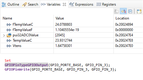
if i set the GPIO_PORTE_BASE, GPIO_PIN_3  to HIGH before initializing internal temperature sensor, everything is good , reading temperature as expected.

But, if not set, there is a difference reading analog values between set or not set.

You can see the following source code. 

How can we fix this ? 

/*
 * hal_adc.c
 *
 *  Created on: 9 May 2016
 *      Author: selami
 */

#include <hal_adc_0.h>
#include <stdint.h>
#include <stdbool.h>
#include "inc/hw_types.h"
#include "inc/hw_generictypes.h"
#include "inc/hw_memmap.h"
#include "inc/hw_ints.h"
#include "inc/hw_gpio.h"
#include "driverlib/interrupt.h"
#include "driverlib/sysctl.h"
#include "driverlib/gpio.h"
#include "driverlib/pin_map.h"
#include "driverlib/adc.h"
#include "driverlib/sysctl.h"
//*****************************************************************************
//
// This is the data acquisition module.  It performs acquisition of data from
// selected channels, starting and stopping data logging, storing acquired
// data.
//
// PINS -- >> E3   AIN0
//*****************************************************************************

void internal_TemperatureSensorInit(void)
{
    //
    // The ADC0 peripheral must be enabled for use.
    //
    SysCtlPeripheralEnable(SYSCTL_PERIPH_ADC0);
    SysCtlPeripheralReset(SYSCTL_PERIPH_ADC0);

    //
    // Enable sample sequence 3 with a processor signal trigger.  Sequence 3
    // will do a single sample when the processor sends a singal to start the
    // conversion.  Each ADC module has 4 programmable sequences, sequence 0
    // to sequence 3.  This example is arbitrarily using sequence 3.
    //
    ADCSequenceConfigure(ADC0_BASE, 3, ADC_TRIGGER_PROCESSOR, 0);

    //
    // Configure step 0 on sequence 3.  Sample the temperature sensor
    // (ADC_CTL_TS) and configure the interrupt flag (ADC_CTL_IE) to be set
    // when the sample is done.  Tell the ADC logic that this is the last
    // conversion on sequence 3 (ADC_CTL_END).  Sequence 3 has only one
    // programmable step.  Sequence 1 and 2 have 4 steps, and sequence 0 has
    // 8 programmable steps.  Since we are only doing a single conversion using
    // sequence 3 we will only configure step 0.  For more information on the
    // ADC sequences and steps, reference the datasheet.
    //
    ADCSequenceStepConfigure(ADC0_BASE, 3, 0, ADC_CTL_TS | ADC_CTL_IE |
                             ADC_CTL_END);

    //
    // Since sample sequence 3 is now configured, it must be enabled.
    //
    ADCSequenceEnable(ADC0_BASE, 3);

    //
    // Clear the interrupt status flag.  This is done to make sure the
    // interrupt flag is cleared before we sample.
    //
    ADCIntClear(ADC0_BASE, 3);
}

float internal_TemperatureSensorRead(void)
{
    //
    // These variables are used to store the temperature conversions for
    // Celsius and Fahrenheit.
    //
    float Vtens;
    //
    // This array is used for storing the data read from the ADC FIFO. It
    // must be as large as the FIFO for the sequencer in use.  This example
    // uses sequence 3 which has a FIFO depth of 1.  If another sequence
    // was used with a deeper FIFO, then the array size must be changed.
    //
    uint32_t pui32ADC0Value[1];
    //
    // These variables are used to store the temperature conversions for
    // Celsius and Fahrenheit.
    //
    static float fTempValueC = 0;
    static float fTempValueF;
    float TempValueC;
    //
    // Trigger the ADC conversion.
    //
    ADCProcessorTrigger(ADC0_BASE, 3);

    //
    // Wait for conversion to be completed.
    //
    while(!ADCIntStatus(ADC0_BASE, 3, false))
    {
    }

    //
    // Clear the ADC interrupt flag.
    //
    ADCIntClear(ADC0_BASE, 3);

    //
    // Read ADC Value.
    //
    ADCSequenceDataGet(ADC0_BASE, 3, pui32ADC0Value);

    Vtens = (float)( ((float )pui32ADC0Value[0] * 3.3) / 4096);
    //
    // Use non-calibrated conversion provided in the data sheet.  Make
    // sure you divide last to avoid dropout.
    //
    // TEMP = 75*(2.7 - VTSENS) - 55

    TempValueC = 75 * (2.7 - Vtens) - 55;

    //filter
    fTempValueC = fTempValueC + (TempValueC - fTempValueC) * 0.25;

    return fTempValueC;
}


void test_Internal_Temperature()
{

    GPIOPinTypeGPIOOutput(GPIO_PORTE_BASE, GPIO_PIN_3);
    GPIOPinWrite(GPIO_PORTE_BASE, GPIO_PIN_3, GPIO_PIN_3);

    internal_TemperatureSensorInit();
    while(1)
    {
        internal_TemperatureSensorRead();
    }
}

  • Hello Selami,

    Use the following for your ADC configuration:

        ADCSequenceStepConfigure(ADC0_BASE, 3, 0, ADC_CTL_TS | ADC_CTL_IE |
        						 ADC_CTL_SHOLD_16 | ADC_CTL_END);

    The reasoning for this is explained on this E2E thread: https://e2e.ti.com/support/microcontrollers/other/f/908/p/775222/2876444#2876444

    The quick summary is: "It does appear that between samples the analog multiplexor switch defaults to channel 0, which means the voltage on pin PE3 can affect the ADC results if the source resistance is too high for the allocated sample time. The source resistance on the temperature sensor is high. Running the ADC at 16MHz and using only a 4 clock sample period, I saw about a 10C difference when PE3 was tied to 3.3V as opposed to GND."

    There are more details about fundamental ADC operation within the thread. Let me know if you have any questions about the discussion that occurred there.

  • Thank you for your response.

    I looked at the discussion.

    i tried the following code :   

    ADCSequenceStepConfigure(ADC0_BASE, 3, 0, ADC_CTL_TS |  ADC_CTL_SHOLD_16 | ADC_CTL_END);

    Also tested with SHOLD_64, but there is no result. it is same.

    Also tried : ADCClockConfigSet(ADC0_BASE, ADC_CLOCK_SRC_PLL | ADC_CLOCK_RATE_FULL, ADC_CLOCK_DIVIDER);

    Also tried : for (i=3; i>0; i--) //run 3 loops to meet setling time of temperature sensor internally

    Any configuration i did , There is no result. 

  • Hello Selami,

    Using this code I was able to see the correct results regardless of GPIOPinWrite being used to set PE3 high or not:

    #include <stdint.h>
    #include <stdbool.h>
    #include "inc/hw_types.h"
    #include "inc/hw_memmap.h"
    #include "inc/hw_ints.h"
    #include "inc/hw_gpio.h"
    #include "driverlib/interrupt.h"
    #include "driverlib/sysctl.h"
    #include "driverlib/gpio.h"
    #include "driverlib/pin_map.h"
    #include "driverlib/adc.h"
    #include "driverlib/sysctl.h"
    #include "driverlib/uart.h"
    #include "utils/uartstdio.h"
    
    //*****************************************************************************
    //
    // System clock rate in Hz.
    //
    //*****************************************************************************
    uint32_t g_ui32SysClock;
    
    //*****************************************************************************
    //
    // This is the data acquisition module.  It performs acquisition of data from
    // selected channels, starting and stopping data logging, storing acquired
    // data.
    //
    // PINS -- >> E3   AIN0
    //*****************************************************************************
    
    void internal_TemperatureSensorInit(void)
    {
        //
        // The ADC0 peripheral must be enabled for use.
        //
        SysCtlPeripheralEnable(SYSCTL_PERIPH_ADC0);
        SysCtlPeripheralReset(SYSCTL_PERIPH_ADC0);
    //
    //    //
    //    // Set the clock for both ADCs (ADC1_BASE sets the clock for both ADCs)
    //    // ADC_CLOCK_DIVIDER == 30 -> set the ADC clock to 16MHz corresponding to 1Msp/s
    //    // ADC_CLOCK_DIVIDER == 15 -> set the ADC clock to 32MHz corresponding to 2Msp/s
    //    //
    //    ADCClockConfigSet(ADC0_BASE, ADC_CLOCK_SRC_PLL | ADC_CLOCK_RATE_FULL, 30);
    
        //
        // Enable sample sequence 3 with a processor signal trigger.  Sequence 3
        // will do a single sample when the processor sends a singal to start the
        // conversion.  Each ADC module has 4 programmable sequences, sequence 0
        // to sequence 3.  This example is arbitrarily using sequence 3.
        //
        ADCSequenceConfigure(ADC0_BASE, 3, ADC_TRIGGER_PROCESSOR, 0);
    
        //
        // Configure step 0 on sequence 3.  Sample the temperature sensor
        // (ADC_CTL_TS) and configure the interrupt flag (ADC_CTL_IE) to be set
        // when the sample is done.  Tell the ADC logic that this is the last
        // conversion on sequence 3 (ADC_CTL_END).  Sequence 3 has only one
        // programmable step.  Sequence 1 and 2 have 4 steps, and sequence 0 has
        // 8 programmable steps.  Since we are only doing a single conversion using
        // sequence 3 we will only configure step 0.  For more information on the
        // ADC sequences and steps, reference the datasheet.
        //
        ADCSequenceStepConfigure(ADC0_BASE, 3, 0, ADC_CTL_TS | ADC_CTL_IE |
        						 ADC_CTL_SHOLD_16 | ADC_CTL_END);
        //
        // Since sample sequence 3 is now configured, it must be enabled.
        //
        ADCSequenceEnable(ADC0_BASE, 3);
    
        //
        // Clear the interrupt status flag.  This is done to make sure the
        // interrupt flag is cleared before we sample.
        //
        ADCIntClear(ADC0_BASE, 3);
    }
    
    float internal_TemperatureSensorRead(void)
    {
        //
        // These variables are used to store the temperature conversions for
        // Celsius and Fahrenheit.
        //
        float Vtens;
        //
        // This array is used for storing the data read from the ADC FIFO. It
        // must be as large as the FIFO for the sequencer in use.  This example
        // uses sequence 3 which has a FIFO depth of 1.  If another sequence
        // was used with a deeper FIFO, then the array size must be changed.
        //
        uint32_t pui32ADC0Value[1];
        //
        // These variables are used to store the temperature conversions for
        // Celsius and Fahrenheit.
        //
        static float fTempValueC = 0;
        static float fTempValueF;
        float TempValueC;
    
        //
        // Trigger the ADC conversion.
        //
        ADCProcessorTrigger(ADC0_BASE, 3);
    
        //
        // Wait for conversion to be completed.
        //
        while(!ADCIntStatus(ADC0_BASE, 3, false))
        {
        }
    
        //
        // Clear the ADC interrupt flag.
        //
        ADCIntClear(ADC0_BASE, 3);
    
        //
        // Read ADC Value.
        //
        ADCSequenceDataGet(ADC0_BASE, 3, pui32ADC0Value);
    
        Vtens = (float)( ((float )pui32ADC0Value[0] * 3.3) / 4096);
        //
        // Use non-calibrated conversion provided in the data sheet.  Make
        // sure you divide last to avoid dropout.
        //
        // TEMP = 75*(2.7 - VTSENS) - 55
    
        TempValueC = 75 * (2.7 - Vtens) - 55;
    
        //filter
        fTempValueC = fTempValueC + (TempValueC - fTempValueC) * 0.25;
    
        //
        // Display the temperature value on the console.
        //
        UARTprintf("Temperature = %2d*C (Filtered) or %2d*C (Non-Filtered)\r", (uint32_t) fTempValueC,
        		(uint32_t) TempValueC);
    
        return fTempValueC;
    }
    
    //*****************************************************************************
    //
    // This function sets up UART0 to be used for a console to display information
    // as the example is running.
    //
    //*****************************************************************************
    void
    InitConsole(void)
    {
        //
        // Enable GPIO port A which is used for UART0 pins.
        // TODO: change this to whichever GPIO port you are using.
        //
        SysCtlPeripheralEnable(SYSCTL_PERIPH_GPIOA);
    
        //
        // Configure the pin muxing for UART0 functions on port A0 and A1.
        // This step is not necessary if your part does not support pin muxing.
        // TODO: change this to select the port/pin you are using.
        //
        GPIOPinConfigure(GPIO_PA0_U0RX);
        GPIOPinConfigure(GPIO_PA1_U0TX);
    
        //
        // Enable UART0 so that we can configure the clock.
        //
        SysCtlPeripheralEnable(SYSCTL_PERIPH_UART0);
    
        //
        // Use the internal 16MHz oscillator as the UART clock source.
        //
        UARTClockSourceSet(UART0_BASE, UART_CLOCK_PIOSC);
    
        //
        // Select the alternate (UART) function for these pins.
        // TODO: change this to select the port/pin you are using.
        //
        GPIOPinTypeUART(GPIO_PORTA_BASE, GPIO_PIN_0 | GPIO_PIN_1);
    
        //
        // Initialize the UART for console I/O.
        //
        UARTStdioConfig(0, 115200, 16000000);
    }
    
    void main()
    {
        //
        // Run from the PLL at 120 MHz.
        // Note: SYSCTL_CFG_VCO_240 is a new setting provided in TivaWare 2.2.x and
        // later to better reflect the actual VCO speed due to SYSCTL#22.
        //
        g_ui32SysClock = SysCtlClockFreqSet((SYSCTL_XTAL_25MHZ |
                                                 SYSCTL_OSC_MAIN |
                                                 SYSCTL_USE_PLL |
                                                 SYSCTL_CFG_VCO_240), 120000000);
    
        //
        // Set up the serial console to use for displaying messages.  This is just
        // for this example program and is not needed for ADC operation.
        //
        InitConsole();
    
        //
        // Enable the GPIO port that is used for the on-board LED.
        //
        SysCtlPeripheralEnable(SYSCTL_PERIPH_GPIOE);
    
        GPIOPinTypeGPIOOutput(GPIO_PORTE_BASE, GPIO_PIN_3);
        GPIOPinWrite(GPIO_PORTE_BASE, GPIO_PIN_3, GPIO_PIN_3);
    
        internal_TemperatureSensorInit();
    
        while(1)
        {
            internal_TemperatureSensorRead();
        }
    
    }
    

  • Dear Jacobi,

    Sorry for late.

    It working now. We fixed this.

    Just, for calibration we edited this part as the following :

    // 65 : calibrated value according to FLIR TG167
    TempValueC = 75 * (2.7 - Vtens) - 65;

    Thank you very much for your valuable reply.