This thread has been locked.

If you have a related question, please click the "Ask a related question" button in the top right corner. The newly created question will be automatically linked to this question.

CCS/TM4C123GH6PM: TM4C123GH6PM

Part Number: TM4C123GH6PM
Other Parts Discussed in Thread: EK-TM4C123GXL

Tool/software: Code Composer Studio

I'm trying to interface MCP401XEV EVALUATION BOARD (which has digital Resistor inside, MCP40D18) with my microcontroller Tiva C Launchpad(TM4C123GH6PM) with the I2C Interface:

Master : I2C module 0, which is GPIO Port B , pin 2(SCL) pin 3(SDA).

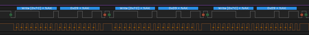
Slave : digital POT(MCP401XEV) which has Slave address (0x7C)

i want to send one single Byte to my digital POT and then read the V(out) from it.

each time i measure i see the middle value , which means that no data transmitted by Master and received by Slave and when i see the value of I2CMDR Register in CCS i notice that this register does not update at all .

i saw that somebody else had the same problem and i did what i had to , like make a breakpoint befor and after writing to I2CMDR :: I2CMasterDataPut(uint32_t ui32Base,uint8_t ui8Data) or setting the GPIO_DEN for PB2,PB3 but it didn't work.

if somebody can help me i would be very very thankfull because this problem for such a simple code and simple use of I2C interface driving me crazy .

#include <stdarg.h>
#include <stdbool.h>
#include <stdint.h>
#include "inc/hw_i2c.h"
#include "inc/hw_memmap.h"
#include "inc/hw_types.h"
#include "inc/hw_gpio.h"
#include "driverlib/i2c.h"
#include "driverlib/sysctl.h"
#include "driverlib/gpio.h"
#include "driverlib/pin_map.h"

#define GPIO_PORTB_DEN_R    (*((volatile unsigned long *)0x4000551C)) // GPIO Digital Enable(8bits)//


void InitI2C0(void){
    //enable I2C module 0
    SysCtlPeripheralEnable(SYSCTL_PERIPH_I2C0);

    //reset module
    SysCtlPeripheralReset(SYSCTL_PERIPH_I2C0);

    //enable GPIO peripheral that contains I2C 0
    SysCtlPeripheralEnable(SYSCTL_PERIPH_GPIOB);

    //GPIO_PORTB_DEN_R |= 0xFF;       // enable digital I/O on PB2,3 (i just wanted to show that i setted also DEN for PB2,PB3)

    // Configure the pin muxing for I2C0 functions on port B2 and B3.
    GPIOPinConfigure(GPIO_PB2_I2C0SCL);
    GPIOPinConfigure(GPIO_PB3_I2C0SDA);

    // Select the I2C function for these pins.
    GPIOPinTypeI2CSCL(GPIO_PORTB_BASE, GPIO_PIN_2);
    GPIOPinTypeI2C(GPIO_PORTB_BASE, GPIO_PIN_3);

    // Enable and initialize the I2C0 master module.  Use the system clock for
    // the I2C0 module.  The last parameter sets the I2C data transfer rate.
    // If false the data rate is set to 100kbps and if true the data rate will
    // be set to 400kbps.
    I2CMasterInitExpClk(I2C0_BASE, SysCtlClockGet(), false);

    //clear I2C FIFOs
    HWREG(I2C0_BASE + I2C_O_FIFOCTL) = 80008000;
}


int main(void){
SysCtlClockSet(SYSCTL_SYSDIV_5 | SYSCTL_USE_PLL | SYSCTL_XTAL_16MHZ | SYSCTL_OSC_MAIN); //Set Clock Frequency at 50MHz

InitI2C0();

I2CMasterSlaveAddrSet(I2C0_BASE, 0x7C, false);

I2CMasterDataPut(I2C0_BASE, 0x5A);

I2CMasterControl(I2C0_BASE, I2C_MASTER_CMD_SINGLE_SEND);

while(I2CMasterBusy(I2C0_BASE));

}

  • Hello Mohammad,

    Few comments here:

    1) Are there pull-up resistors installed on the MCP401XEV  EVM? The EK-TM4C123GXL does not have pull-ups installed, and pull-up resistors are required for I2C.

    Mohammadhossein Beigi said:
    each time i measure i see the middle value , which means that no data transmitted by Master and received by Slave and when i see the value of I2CMDR Register in CCS i notice that this register does not update at all .

    What do you mean middle value? There is no slave RX process in place so I am not even sure what this means. Is the other EVM reporting what it receives?

    Do you have an o-scope you can use to check the I2C lines to see if data is sent?

  • hello Ralph,

    i installed the external pull-up resistor by my self on the breadborad and for supplying them , i used (3.3 (v) pin) from the launchpad. i tried diffrent reng of resistor , from 1k k to 6k8 and this time i didn't use MCP401XEV .

    i tried without the digital POT and with o-scope just firs to see if any data transfer on not,  but i see the voltage level always high(3.3(v)more and less ) , and it means no data is transfering !!

    Ralph Jacobi said:
    What do you mean middle value? There is no slave RX process in place so I am not even sure what this means. Is the other EVM reporting what it receives?

    in the middle i ment for MCP401XEV. 

    as default this digital POT shows V(out) the half of the value of given voltage.  i ment the middle value of given voltage. as i was giving 3.3(v) it was showing me 1.63(v). and that means the interfacing data with I2C module  was not successful, because i was giving other values . 

    i even had a look at spma073.pdf and i changed my code to what you see down. and still does NOT working.

    #include <stdarg.h>
    #include <stdbool.h>
    #include <stdint.h>
    #include "inc/hw_i2c.h"
    #include "inc/hw_memmap.h"
    #include "inc/hw_types.h"
    #include "inc/hw_gpio.h"
    #include "driverlib/i2c.h"
    #include "driverlib/sysctl.h"
    #include "driverlib/gpio.h"
    #include "driverlib/pin_map.h"
    
    void InitI2C0(void){
        SysCtlPeripheralEnable(SYSCTL_PERIPH_GPIOB);
        while(!SysCtlPeripheralReady(SYSCTL_PERIPH_GPIOB));
        GPIOPadConfigSet(GPIO_PORTB_BASE,/*GPIO_PIN_2 |*/ GPIO_PIN_3,GPIO_STRENGTH_8MA,GPIO_PIN_TYPE_OD);
        GPIOPinConfigure(GPIO_PB2_I2C0SCL);
        GPIOPinConfigure(GPIO_PB3_I2C0SDA);
        GPIOPinTypeI2C(GPIO_PORTB_BASE, GPIO_PIN_3);
        GPIOPinTypeI2CSCL(GPIO_PORTB_BASE, GPIO_PIN_2);
        // Select the I2C function for these pins.
        SysCtlPeripheralDisable(SYSCTL_PERIPH_I2C0);
        SysCtlPeripheralReset(SYSCTL_PERIPH_I2C0);
        SysCtlPeripheralEnable(SYSCTL_PERIPH_I2C0);
        while(!SysCtlPeripheralReady(SYSCTL_PERIPH_I2C0));
        I2CMasterInitExpClk(I2C0_BASE, SysCtlClockGet(), false);
    
    }
    
    void main(void){
    
    SysCtlClockSet(SYSCTL_SYSDIV_5 | SYSCTL_USE_PLL | SYSCTL_XTAL_16MHZ | SYSCTL_OSC_MAIN); //Set Clock Frequency at 20MHz
    while(1){
    void InitI2C0();
    I2CMasterIntEnableEx(I2C0_BASE, (I2C_MASTER_INT_ARB_LOST |
    I2C_MASTER_INT_STOP | I2C_MASTER_INT_NACK |
    I2C_MASTER_INT_TIMEOUT | I2C_MASTER_INT_DATA));
    
    #define SLAVE_ADDRESS_EXT 0x7C
    // Send the Slave Address with RnW as Transmit
    // and First Data Byte. Based on Number of bytes the
    // command would be either START or FINISH
    //
    I2CMasterSlaveAddrSet(I2C0_BASE, SLAVE_ADDRESS_EXT, false);
    I2CMasterDataPut(I2C0_BASE, 0x09);
    I2CMasterControl(I2C0_BASE, I2C_MASTER_CMD_SINGLE_SEND);
    while(I2CMasterBusy(I2C0_BASE));
    }
    }
    

  • Hello Mohammad,

    You mention spma073, but that is for TM4C129x MCU's, and you are using TM4C123x. So those changes don't necessarily apply here.

    Infact, I don't agree with many of the code changes you have, it should look like the following (which is almost identical to your initial post):

    #include <stdarg.h>
    #include <stdbool.h>
    #include <stdint.h>
    #include "inc/hw_i2c.h"
    #include "inc/hw_memmap.h"
    #include "inc/hw_types.h"
    #include "inc/hw_gpio.h"
    #include "driverlib/i2c.h"
    #include "driverlib/sysctl.h"
    #include "driverlib/gpio.h"
    #include "driverlib/pin_map.h"
    
    void InitI2C0(void){
        SysCtlPeripheralEnable(SYSCTL_PERIPH_GPIOB);
        while(!SysCtlPeripheralReady(SYSCTL_PERIPH_GPIOB));
        GPIOPinConfigure(GPIO_PB2_I2C0SCL);
        GPIOPinConfigure(GPIO_PB3_I2C0SDA);
        GPIOPinTypeI2C(GPIO_PORTB_BASE, GPIO_PIN_3);
        GPIOPinTypeI2CSCL(GPIO_PORTB_BASE, GPIO_PIN_2);
    
        // Select the I2C function for these pins.
        SysCtlPeripheralDisable(SYSCTL_PERIPH_I2C0);
        SysCtlPeripheralReset(SYSCTL_PERIPH_I2C0);
        SysCtlPeripheralEnable(SYSCTL_PERIPH_I2C0);
        while(!SysCtlPeripheralReady(SYSCTL_PERIPH_I2C0));
    
        I2CMasterInitExpClk(I2C0_BASE, SysCtlClockGet(), false);
    }
    
    #define SLAVE_ADDRESS_EXT 0x7C
    
    void main(void){
    
    	SysCtlClockSet(SYSCTL_SYSDIV_5 | SYSCTL_USE_PLL | SYSCTL_XTAL_16MHZ | SYSCTL_OSC_MAIN); //Set Clock Frequency at 20MHz
    
    	InitI2C0();
    
    	while(1){
    		// Send the Slave Address with RnW as Transmit
    		// and First Data Byte. Based on Number of bytes the
    		// command would be either START or FINISH
    		//
    		I2CMasterSlaveAddrSet(I2C0_BASE, SLAVE_ADDRESS_EXT, false);
    
    		I2CMasterDataPut(I2C0_BASE, 0x09);
    
    		I2CMasterControl(I2C0_BASE, I2C_MASTER_CMD_SINGLE_SEND);
    
    		while(I2CMasterBusy(I2C0_BASE));
    	}
    }

    I ran that code and I was able to see data:

    As long as you have resistors on the pins, you would see the initial command go out on the bus. That capture was taken with no slave device present on the LaunchPad, just the pull-up resistors.