Part Number: EK-TM4C1294XL
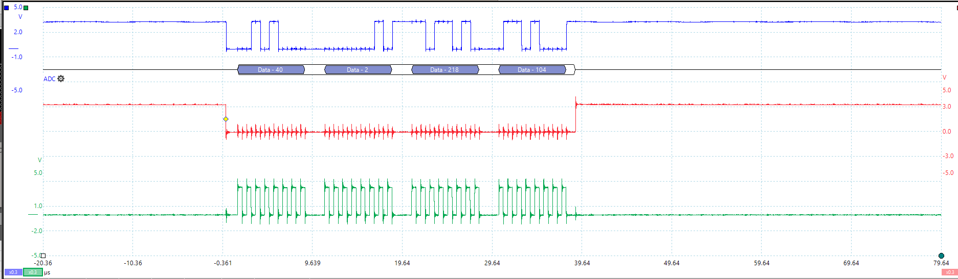
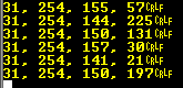
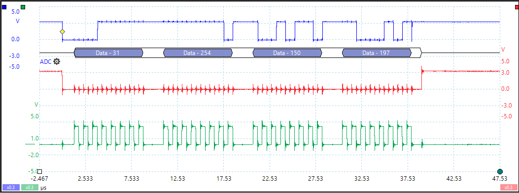
I am attempting to use SPI communication to try and obtain ADC readings from an LTC2400. I am having an issue obtaining reliable MISO data from the ADC that remotely matches the protocol decoding on my scope. I am using the LTC2400 with an external SPI clock and am controlling the CS pin manually. Four 8 bit SPI reads are performed and I am comparing the results to that obtained on my oscilloscope. For instance here are 11 readings:
| TI MCU | Scope | Reading | ||||||
| [0] | [1] | [2] | [3] | [0] | [1] | [2] | [3] | |
| 2 | 246 | 241 | 40 | 40 | 2 | 218 | 104 | 1 |
| 3 | 7 | 214 | 40 | 40 | 3 | 11 | 17 | 2 |
| 3 | 11 | 67 | 40 | 40 | 3 | 3 | 13 | 3 |
| 3 | 16 | 89 | 40 | 40 | 2 | 249 | 100 | 4 |
| 3 | 9 | 3 | 40 | 40 | 2 | 252 | 212 | 5 |
| 2 | 251 | 119 | 40 | 40 | 3 | 4 | 33 | 6 |
| 3 | 4 | 33 | 40 | 40 | 2 | 251 | 119 | 7 |
| 2 | 252 | 212 | 40 | 40 | 3 | 9 | 3 | 8 |
| 2 | 249 | 100 | 40 | 40 | 3 | 16 | 89 | 9 |
| 3 | 3 | 13 | 40 | 40 | 3 | 11 | 67 | 10 |
| 3 | 11 | 13 | 11 | 40 | 3 | 7 | 214 |
11 |
A screen shot of the SDO on the blue channel, CS on the red channel, and SCK on the green channel.
I used spi_master.c example in the TIVA documentation. Attached is the code I am using to read the data from the ADC. The function that does the adc reads is called read_adc().
//*****************************************************************************
//
// pinout.c - Function to configure the device pins on the EK-TM4C1294XL.
//
// Copyright (c) 2013-2017 Texas Instruments Incorporated.  All rights reserved.
// Software License Agreement
//
// Texas Instruments (TI) is supplying this software for use solely and
// exclusively on TI's microcontroller products. The software is owned by
// TI and/or its suppliers, and is protected under applicable copyright
// laws. You may not combine this software with "viral" open-source
// software in order to form a larger program.
//
// THIS SOFTWARE IS PROVIDED "AS IS" AND WITH ALL FAULTS.
// NO WARRANTIES, WHETHER EXPRESS, IMPLIED OR STATUTORY, INCLUDING, BUT
// NOT LIMITED TO, IMPLIED WARRANTIES OF MERCHANTABILITY AND FITNESS FOR
// A PARTICULAR PURPOSE APPLY TO THIS SOFTWARE. TI SHALL NOT, UNDER ANY
// CIRCUMSTANCES, BE LIABLE FOR SPECIAL, INCIDENTAL, OR CONSEQUENTIAL
// DAMAGES, FOR ANY REASON WHATSOEVER.
//
// This is part of revision 2.1.4.178 of the EK-TM4C1294XL Firmware Package.
//
//*****************************************************************************


#include <stdbool.h>
#include <stdint.h>
#include "inc/hw_gpio.h"
#include "inc/hw_memmap.h"
#include "inc/hw_types.h"
#include "driverlib/gpio.h"
#include "driverlib/pin_map.h"
#include "driverlib/rom.h"
#include "driverlib/rom_map.h"
#include "driverlib/sysctl.h"
#include "drivers/pinout.h"
#include "driverlib/ssi.h"

//*****************************************************************************
//
//! \addtogroup pinout_api
//! @{
//
//*****************************************************************************

//*****************************************************************************
//
//! Configures the device pins for the standard usages on the EK-TM4C1294XL.
//!
//! \param bEthernet is a boolean used to determine function of Ethernet pins.
//! If true Ethernet pins are  configured as Ethernet LEDs.  If false GPIO are
//! available for application use.
//! \param bUSB is a boolean used to determine function of USB pins. If true USB
//! pins are configured for USB use.  If false then USB pins are available for
//! application use as GPIO.
//!
//! This function enables the GPIO modules and configures the device pins for
//! the default, standard usages on the EK-TM4C1294XL.  Applications that
//! require alternate configurations of the device pins can either not call
//! this function and take full responsibility for configuring all the device
//! pins, or can reconfigure the required device pins after calling this
//! function.
//!
//! \return None.
//
//*****************************************************************************
void
PinoutSet(bool bEthernet, bool bUSB)
{


    //
    // For this example SSI0 is used with PortA[5:2].  The actual port and pins
    // used may be different on your part, consult the data sheet for more
    // information.  GPIO port A needs to be enabled so these pins can be used.
    // TODO: change this to whichever GPIO port you are using.
    //
    ROM_SysCtlPeripheralEnable(SYSCTL_PERIPH_GPIOA);
    //
    // Enable all the other GPIO peripherals.
    //
    ROM_SysCtlPeripheralEnable(SYSCTL_PERIPH_GPIOB);
    ROM_SysCtlPeripheralEnable(SYSCTL_PERIPH_GPIOC);
    ROM_SysCtlPeripheralEnable(SYSCTL_PERIPH_GPIOD);
    ROM_SysCtlPeripheralEnable(SYSCTL_PERIPH_GPIOE);
    ROM_SysCtlPeripheralEnable(SYSCTL_PERIPH_GPIOF);
    ROM_SysCtlPeripheralEnable(SYSCTL_PERIPH_GPIOG);
    ROM_SysCtlPeripheralEnable(SYSCTL_PERIPH_GPIOH);
    ROM_SysCtlPeripheralEnable(SYSCTL_PERIPH_GPIOJ);
    ROM_SysCtlPeripheralEnable(SYSCTL_PERIPH_GPIOK);
    ROM_SysCtlPeripheralEnable(SYSCTL_PERIPH_GPIOL);
    ROM_SysCtlPeripheralEnable(SYSCTL_PERIPH_GPIOM);
    ROM_SysCtlPeripheralEnable(SYSCTL_PERIPH_GPION);
    ROM_SysCtlPeripheralEnable(SYSCTL_PERIPH_GPIOP);
    ROM_SysCtlPeripheralEnable(SYSCTL_PERIPH_GPIOQ);

    //
    // The SSI0 peripheral must be enabled for use.
    //
    //SysCtlPeripheralEnable(SYSCTL_PERIPH_SSI0);
    ROM_SysCtlPeripheralEnable(SYSCTL_PERIPH_SSI0);

    //
    // PA0-1 are used for UART0.
    //
    ROM_GPIOPinConfigure(GPIO_PA0_U0RX);
    ROM_GPIOPinConfigure(GPIO_PA1_U0TX);
    ROM_GPIOPinTypeUART(GPIO_PORTA_BASE, GPIO_PIN_0 | GPIO_PIN_1);

    //
    // Configure the pin muxing for SSI0 functions on port A2, A3, A4, and A5.
    // This step is not necessary if your part does not support pin muxing.
    // TODO: change this to select the port/pin you are using.
    //
    ROM_GPIOPinConfigure(GPIO_PA2_SSI0CLK);
    ROM_GPIOPinConfigure(GPIO_PA3_SSI0FSS);
    ROM_GPIOPinConfigure(GPIO_PA4_SSI0XDAT0);
    ROM_GPIOPinConfigure(GPIO_PA5_SSI0XDAT1);

    //
    // Configure the GPIO settings for the SSI pins.  This function also gives
    // control of these pins to the SSI hardware.  Consult the data sheet to
    // see which functions are allocated per pin.
    // The pins are assigned as follows:
    //      PA5 - SSI0Tx
    //      PA4 - SSI0Rx
    //      PA3 - SSI0Fss
    //      PA2 - SSI0CLK
    // TODO: change this to select the port/pin you are using.
    //
    ROM_GPIOPinTypeSSI(GPIO_PORTA_BASE, GPIO_PIN_5 | GPIO_PIN_4 | GPIO_PIN_3 | GPIO_PIN_2);

    //
    // Configure and enable the SSI port for SPI master mode.  Use SSI0,
    // system clock supply, idle clock level low and active low clock in
    // freescale SPI mode, master mode, 1MHz SSI frequency, and 8-bit data.
    // For SPI mode, you can set the polarity of the SSI clock when the SSI
    // unit is idle.  You can also configure what clock edge you want to
    // capture data on.  Please reference the datasheet for more information on
    // the different SPI modes.

    //
    // PB0-1/PD6/PL6-7 are used for USB.
    // PQ4 can be used as a power fault detect on this board but it is not
    // the hardware peripheral power fault input pin.
    //
    if(bUSB)
    {
        HWREG(GPIO_PORTD_BASE + GPIO_O_LOCK) = GPIO_LOCK_KEY;
        HWREG(GPIO_PORTD_BASE + GPIO_O_CR) = 0xff;
        ROM_GPIOPinConfigure(GPIO_PD6_USB0EPEN);
        ROM_GPIOPinTypeUSBAnalog(GPIO_PORTB_BASE, GPIO_PIN_0 | GPIO_PIN_1);
        ROM_GPIOPinTypeUSBDigital(GPIO_PORTD_BASE, GPIO_PIN_6);
        ROM_GPIOPinTypeUSBAnalog(GPIO_PORTL_BASE, GPIO_PIN_6 | GPIO_PIN_7);
        ROM_GPIOPinTypeGPIOInput(GPIO_PORTQ_BASE, GPIO_PIN_4);
    }
    else
    {
        //
        // Keep the default config for most pins used by USB.
        // Add a pull down to PD6 to turn off the TPS2052 switch
        //
        ROM_GPIOPinTypeGPIOInput(GPIO_PORTD_BASE, GPIO_PIN_6);
        MAP_GPIOPadConfigSet(GPIO_PORTD_BASE, GPIO_PIN_6, GPIO_STRENGTH_2MA,
                             GPIO_PIN_TYPE_STD_WPD);

    }

    //
    // PF0/PF4 are used for Ethernet LEDs.
    //
    if(bEthernet)
    {
        //
        // this app wants to configure for ethernet LED function.
        //
        ROM_GPIOPinConfigure(GPIO_PF0_EN0LED0);
        ROM_GPIOPinConfigure(GPIO_PF4_EN0LED1);

        GPIOPinTypeEthernetLED(GPIO_PORTF_BASE, GPIO_PIN_0 | GPIO_PIN_4);

    }
    else
    {

        //
        // This app does not want Ethernet LED function so configure as
        // standard outputs for LED driving.
        //
        ROM_GPIOPinTypeGPIOOutput(GPIO_PORTF_BASE, GPIO_PIN_0 | GPIO_PIN_4);

        //
        // Default the LEDs to OFF.
        //
        ROM_GPIOPinWrite(GPIO_PORTF_BASE, GPIO_PIN_0 | GPIO_PIN_4, 0);
        MAP_GPIOPadConfigSet(GPIO_PORTF_BASE, GPIO_PIN_0 | GPIO_PIN_4,
                             GPIO_STRENGTH_12MA, GPIO_PIN_TYPE_STD);


    }

    ROM_GPIOPinTypeGPIOOutput(GPIO_PORTC_BASE, GPIO_PIN_7);
    ROM_GPIOPinTypeGPIOOutput(GPIO_PORTC_BASE, GPIO_PIN_6);
    ROM_GPIOPinTypeGPIOOutput(GPIO_PORTL_BASE, GPIO_PIN_0);
    ROM_GPIOPinTypeGPIOOutput(GPIO_PORTL_BASE, GPIO_PIN_1);
    ROM_GPIOPinTypeGPIOOutput(GPIO_PORTL_BASE, GPIO_PIN_2);
    ROM_GPIOPinTypeGPIOOutput(GPIO_PORTL_BASE, GPIO_PIN_3);
    ROM_GPIOPinTypeGPIOOutput(GPIO_PORTH_BASE, GPIO_PIN_2);
    ROM_GPIOPinTypeGPIOOutput(GPIO_PORTH_BASE, GPIO_PIN_3);
    ROM_GPIOPinTypeGPIOOutput(GPIO_PORTN_BASE, GPIO_PIN_2);
    ROM_GPIOPinTypeGPIOOutput(GPIO_PORTN_BASE, GPIO_PIN_3);
    ROM_GPIOPinTypeGPIOOutput(GPIO_PORTP_BASE, GPIO_PIN_2);
    ROM_GPIOPinTypeGPIOOutput(GPIO_PORTP_BASE, GPIO_PIN_4);

    //
    // PJ0 and J1 are used for user buttons
    //
    ROM_GPIOPinTypeGPIOInput(GPIO_PORTJ_BASE, GPIO_PIN_0 | GPIO_PIN_1);
    ROM_GPIOPinWrite(GPIO_PORTJ_BASE, GPIO_PIN_0 | GPIO_PIN_1, 0);

    //
    // PN0 and PN1 are used for USER LEDs.
    //
    ROM_GPIOPinTypeGPIOOutput(GPIO_PORTN_BASE, GPIO_PIN_0 | GPIO_PIN_1);
    MAP_GPIOPadConfigSet(GPIO_PORTN_BASE, GPIO_PIN_0 | GPIO_PIN_1,
                             GPIO_STRENGTH_12MA, GPIO_PIN_TYPE_STD);

    //
    // Default the LEDs to OFF.
    //
    ROM_GPIOPinWrite(GPIO_PORTN_BASE, GPIO_PIN_0 | GPIO_PIN_1, 0);

}

//*****************************************************************************
//
//! This function writes a state to the LED bank.
//!
//! \param ui32LEDMask is a bit mask for which GPIO should be changed by this
//! call.
//! \param ui32LEDValue is the new value to be applied to the LEDs after the
//! ui32LEDMask is applied.
//!
//! The first parameter acts as a mask.  Only bits in the mask that are set
//! will correspond to LEDs that may change.  LEDs with a mask that is not set
//! will not change. This works the same as GPIOPinWrite. After applying the
//! mask the setting for each unmasked LED is written to the corresponding
//! LED port pin via GPIOPinWrite.
//!
//! \return None.
//
//*****************************************************************************
void
LEDWrite(uint32_t ui32LEDMask, uint32_t ui32LEDValue)
{

    //
    // Check the mask and set or clear the LED as directed.
    //
    if(ui32LEDMask & CLP_D1)
    {
        if(ui32LEDValue & CLP_D1)
        {
            GPIOPinWrite(CLP_D1_PORT, CLP_D1_PIN, CLP_D1_PIN);
        }
        else
        {
            GPIOPinWrite(CLP_D1_PORT, CLP_D1_PIN, 0);
        }
    }

    if(ui32LEDMask & CLP_D2)
    {
        if(ui32LEDValue & CLP_D2)
        {
            GPIOPinWrite(CLP_D2_PORT, CLP_D2_PIN, CLP_D2_PIN);
        }
        else
        {
            GPIOPinWrite(CLP_D2_PORT, CLP_D2_PIN, 0);
        }
    }

    if(ui32LEDMask & CLP_D3)
    {
        if(ui32LEDValue & CLP_D3)
        {
            GPIOPinWrite(CLP_D3_PORT, CLP_D3_PIN, CLP_D3_PIN);
        }
        else
        {
            GPIOPinWrite(CLP_D3_PORT, CLP_D3_PIN, 0);
        }
    }

    if(ui32LEDMask & CLP_D4)
    {
        if(ui32LEDValue & CLP_D4)
        {
            GPIOPinWrite(CLP_D4_PORT, CLP_D4_PIN, CLP_D4_PIN);
        }
        else
        {
            GPIOPinWrite(CLP_D4_PORT, CLP_D4_PIN, 0);
        }
    }
}

//*****************************************************************************
//
//! This function reads the state to the LED bank.
//!
//! \param pui32LEDValue is a pointer to where the LED value will be stored.
//!
//! This function reads the state of the CLP LEDs and stores that state
//! information into the variable pointed to by pui32LEDValue.
//!
//! \return None.
//
//*****************************************************************************
void LEDRead(uint32_t *pui32LEDValue)
{
    *pui32LEDValue = 0;

    //
    // Read the pin state and set the variable bit if needed.
    //
    if(GPIOPinRead(CLP_D4_PORT, CLP_D4_PIN))
    {
        *pui32LEDValue |= CLP_D4;
    }

    //
    // Read the pin state and set the variable bit if needed.
    //
    if(GPIOPinRead(CLP_D3_PORT, CLP_D3_PIN))
    {
        *pui32LEDValue |= CLP_D3;
    }

    //
    // Read the pin state and set the variable bit if needed.
    //
    if(GPIOPinRead(CLP_D2_PORT, CLP_D2_PIN))
    {
        *pui32LEDValue |= CLP_D2;
    }

    //
    // Read the pin state and set the variable bit if needed.
    //
    if(GPIOPinRead(CLP_D1_PORT, CLP_D1_PIN))
    {
        *pui32LEDValue |= CLP_D1;
    }
}

//*****************************************************************************
//
// Close the Doxygen group.
//! @}
//
//*****************************************************************************
//*****************************************************************************
//
// enet_uip.c - Sample WebServer Application for Ethernet Demo
//
// Copyright (c) 2013-2017 Texas Instruments Incorporated. All rights reserved.
// Software License Agreement
//
// Texas Instruments (TI) is supplying this software for use solely and
// exclusively on TI's microcontroller products. The software is owned by
// TI and/or its suppliers, and is protected under applicable copyright
// laws. You may not combine this software with "viral" open-source
// software in order to form a larger program.
//
// THIS SOFTWARE IS PROVIDED "AS IS" AND WITH ALL FAULTS.
// NO WARRANTIES, WHETHER EXPRESS, IMPLIED OR STATUTORY, INCLUDING, BUT
// NOT LIMITED TO, IMPLIED WARRANTIES OF MERCHANTABILITY AND FITNESS FOR
// A PARTICULAR PURPOSE APPLY TO THIS SOFTWARE. TI SHALL NOT, UNDER ANY
// CIRCUMSTANCES, BE LIABLE FOR SPECIAL, INCIDENTAL, OR CONSEQUENTIAL
// DAMAGES, FOR ANY REASON WHATSOEVER.
//
// This is part of revision 2.1.4.178 of the EK-TM4C1294XL Firmware Package.
//
//*****************************************************************************
#include <stdbool.h>
#include <stdint.h>
#include <math.h>
#include "inc/hw_emac.h"
#include "inc/hw_ints.h"
#include "inc/hw_memmap.h"
#include "inc/hw_types.h"
#include "driverlib/debug.h"
#include "driverlib/emac.h"
#include "driverlib/flash.h"
#include "driverlib/interrupt.h"
#include "driverlib/rom.h"
#include "driverlib/rom_map.h"
#include "driverlib/sysctl.h"
#include "driverlib/systick.h"
#include "utils/uartstdio.h"
#include "utils/ustdlib.h"
#include "uip/uip.h"
#include "uip/uip_arp.h"
//#include "httpd/httpd.h"
#include "telnetd/telnetd.h"
#include "dhcpc/dhcpc.h"
#include "drivers/pinout.h"
#include "driverlib/pin_map.h"
#include "driverlib/ssi.h"
#include "driverlib/gpio.h"
//*****************************************************************************
//
//! \addtogroup example_list
//! <h1>Ethernet with uIP (enet_uip)</h1>
//!
//! This example application demonstrates the operation of the Tiva C Series
//! Ethernet controller using the uIP TCP/IP Stack. DHCP is used to obtain
//! an Ethernet address. A basic web site is served over the Ethernet port.
//! The web site displays a few lines of text, and a counter that increments
//! each time the page is sent.
//!
//! UART0, connected to the ICDI virtual COM port and running at 115,200,
//! 8-N-1, is used to display messages from this application.
//!
//! For additional details on uIP, refer to the uIP web page at:
//! http://www.sics.se/~adam/uip/
//
//*****************************************************************************
//*****************************************************************************
//
// Defines for setting up the system clock.
//
//*****************************************************************************
#define SYSTICKHZ CLOCK_CONF_SECOND
#define SYSTICKMS (1000 / SYSTICKHZ)
#define SYSTICKUS (1000000 / SYSTICKHZ)
#define SYSTICKNS (1000000000 / SYSTICKHZ)
//*****************************************************************************
//
// Macro for accessing the Ethernet header information in the buffer.
//
//*****************************************************************************
u8_t g_pui8UIPBuffer[UIP_BUFSIZE + 2];
u8_t *uip_buf = g_pui8UIPBuffer;
#define BUF ((struct uip_eth_hdr *)uip_buf)
//*****************************************************************************
//
// Ethernet DMA descriptors.
//
// Although uIP uses a single buffer, the MAC hardware needs a minimum of
// 3 receive descriptors to operate.
//
//*****************************************************************************
#define NUM_TX_DESCRIPTORS 3
#define NUM_RX_DESCRIPTORS 3
tEMACDMADescriptor g_psRxDescriptor[NUM_TX_DESCRIPTORS];
tEMACDMADescriptor g_psTxDescriptor[NUM_RX_DESCRIPTORS];
uint32_t g_ui32RxDescIndex;
uint32_t g_ui32TxDescIndex;
//*****************************************************************************
//
// Transmit and receive buffers.
//
//*****************************************************************************
#define RX_BUFFER_SIZE 1536
#define TX_BUFFER_SIZE 1536
uint8_t g_pui8RxBuffer[RX_BUFFER_SIZE];
uint8_t g_pui8TxBuffer[TX_BUFFER_SIZE];
//*****************************************************************************
//
// A set of flags. The flag bits are defined as follows:
//
// 0 -> An indicator that a SysTick interrupt has occurred.
// 1 -> An RX Packet has been received.
// 2 -> A TX packet DMA transfer is pending.
// 3 -> A RX packet DMA transfer is pending.
//
//*****************************************************************************
#define FLAG_SYSTICK 0
#define FLAG_RXPKT 1
#define FLAG_TXPKT 2
#define FLAG_RXPKTPEND 3
static volatile uint32_t g_ui32Flags;
//*****************************************************************************
//
// A system tick counter, incremented every SYSTICKMS.
//
//*****************************************************************************
volatile uint32_t g_ui32TickCounter = 0;
//*****************************************************************************
//
// Default TCP/IP Settings for this application.
//
// Default to Link Local address ... (169.254.1.0 to 169.254.254.255). Note:
// This application does not implement the Zeroconf protocol. No ARP query is
// issued to determine if this static IP address is already in use.
//
// Uncomment the following #define statement to enable STATIC IP
// instead of DHCP.
//
//*****************************************************************************
//#define USE_STATIC_IP
#ifndef DEFAULT_IPADDR0
#define DEFAULT_IPADDR0 169
#endif
#ifndef DEFAULT_IPADDR1
#define DEFAULT_IPADDR1 254
#endif
#ifndef DEFAULT_IPADDR2
#define DEFAULT_IPADDR2 19
#endif
#ifndef DEFAULT_IPADDR3
#define DEFAULT_IPADDR3 63
#endif
#ifndef DEFAULT_NETMASK0
#define DEFAULT_NETMASK0 255
#endif
#ifndef DEFAULT_NETMASK1
#define DEFAULT_NETMASK1 255
#endif
#ifndef DEFAULT_NETMASK2
#define DEFAULT_NETMASK2 0
#endif
#ifndef DEFAULT_NETMASK3
#define DEFAULT_NETMASK3 0
#endif
//*****************************************************************************
//
// UIP Timers (in MS)
//
//*****************************************************************************
#define UIP_PERIODIC_TIMER_MS 500
#define UIP_ARP_TIMER_MS 10000
//*****************************************************************************
//
// The error routine that is called if the driver library encounters an error.
//
//*****************************************************************************
void
__error__(char *pcFilename, uint32_t ui32Line)
{
}
//*****************************************************************************
//
// The interrupt handler for the SysTick interrupt.
//
//*****************************************************************************
void
SysTickIntHandler(void)
{
//
// Increment the system tick count.
//
g_ui32TickCounter++;
//
// Indicate that a SysTick interrupt has occurred.
//
HWREGBITW(&g_ui32Flags, FLAG_SYSTICK) = 1;
}
//*****************************************************************************
//
// When using the timer module in UIP, this function is required to return
// the number of ticks. Note that the file "clock-arch.h" must be provided
// by the application, and define CLOCK_CONF_SECONDS as the number of ticks
// per second, and must also define the typedef "clock_time_t".
//
//*****************************************************************************
clock_time_t
clock_time(void)
{
return((clock_time_t)g_ui32TickCounter);
}
//*****************************************************************************
//
// Display a status string on the LCD and also transmit it via the serial port.
//
//*****************************************************************************
void
UpdateStatus(char *pcStatus)
{
//
// Dump that status string to the serial port.
//
UARTprintf("%s\n", pcStatus);
}
//*****************************************************************************
//
// Display the current IP address on the screen and transmit it via the UART.
//
//*****************************************************************************
void
ShowIPAddress(const uip_ipaddr_t sIPAddr)
{
char pcBuffer[24];
usprintf(pcBuffer, "IP: %d.%d.%d.%d", sIPAddr[0] & 0xff,
sIPAddr[0] >> 8, sIPAddr[1] & 0xff, sIPAddr[1] >> 8);
UpdateStatus(pcBuffer);
}
//*****************************************************************************
//
// The interrupt handler for the Ethernet interrupt.
//
//*****************************************************************************
void
EthernetIntHandler(void)
{
uint32_t ui32Temp;
//
// Read and Clear the interrupt.
//
ui32Temp = MAP_EMACIntStatus(EMAC0_BASE, true);
MAP_EMACIntClear(EMAC0_BASE, ui32Temp);
//
// Check to see if an RX Interrupt has occurred.
//
if(ui32Temp & EMAC_INT_RECEIVE)
{
//
// Indicate that a packet has been received.
//
HWREGBITW(&g_ui32Flags, FLAG_RXPKT) = 1;
}
//
// Has the DMA finished transferring a packet to the transmitter?
//
if(ui32Temp & EMAC_INT_TRANSMIT)
{
//
// Indicate that a packet has been sent.
//
HWREGBITW(&g_ui32Flags, FLAG_TXPKT) = 0;
}
}
//*****************************************************************************
//
// Callback for when DHCP client has been configured.
//
//*****************************************************************************
void
dhcpc_configured(const struct dhcpc_state *s)
{
uip_sethostaddr(&s->ipaddr);
uip_setnetmask(&s->netmask);
uip_setdraddr(&s->default_router);
ShowIPAddress(s->ipaddr);
}
//*****************************************************************************
//
// Read a packet from the DMA receive buffer into the uIP packet buffer.
//
//*****************************************************************************
int32_t
PacketReceive(uint32_t ui32Base, uint8_t *pui8Buf, int32_t i32BufLen)
{
int_fast32_t i32FrameLen, i32Loop;
//
// Check the arguments.
//
ASSERT(ui32Base == EMAC0_BASE);
ASSERT(pui8Buf != 0);
ASSERT(i32BufLen > 0);
//
// By default, we assume we got a bad frame.
//
i32FrameLen = 0;
//
// Make sure that we own the receive descriptor.
//
if(!(g_psRxDescriptor[g_ui32RxDescIndex].ui32CtrlStatus & DES0_RX_CTRL_OWN))
{
//
// We own the receive descriptor so check to see if it contains a valid
// frame. Look for a descriptor error, indicating that the incoming
// packet was truncated or, if this is the last frame in a packet,
// the receive error bit.
//
if(!(g_psRxDescriptor[g_ui32RxDescIndex].ui32CtrlStatus &
DES0_RX_STAT_ERR))
{
//
// We have a valid frame so copy the content to the supplied
// buffer. First check that the "last descriptor" flag is set. We
// sized the receive buffer such that it can always hold a valid
// frame so this flag should never be clear at this point but...
//
if(g_psRxDescriptor[g_ui32RxDescIndex].ui32CtrlStatus &
DES0_RX_STAT_LAST_DESC)
{
i32FrameLen =
((g_psRxDescriptor[g_ui32RxDescIndex].ui32CtrlStatus &
DES0_RX_STAT_FRAME_LENGTH_M) >>
DES0_RX_STAT_FRAME_LENGTH_S);
//
// Sanity check. This shouldn't be required since we sized the
// uIP buffer such that it's the same size as the DMA receive
// buffer but, just in case...
//
if(i32FrameLen > i32BufLen)
{
i32FrameLen = i32BufLen;
}
//
// Copy the data from the DMA receive buffer into the provided
// frame buffer.
//
for(i32Loop = 0; i32Loop < i32FrameLen; i32Loop++)
{
pui8Buf[i32Loop] = g_pui8RxBuffer[i32Loop];
}
}
}
//
// Move on to the next descriptor in the chain.
//
g_ui32RxDescIndex++;
if(g_ui32RxDescIndex == NUM_RX_DESCRIPTORS)
{
g_ui32RxDescIndex = 0;
}
//
// Mark the next descriptor in the ring as available for the receiver
// to write into.
//
g_psRxDescriptor[g_ui32RxDescIndex].ui32CtrlStatus = DES0_RX_CTRL_OWN;
}
//
// Return the Frame Length
//
return(i32FrameLen);
}
//*****************************************************************************
//
// Transmit a packet from the supplied buffer.
//
//*****************************************************************************
static int32_t
PacketTransmit(uint32_t ui32Base, uint8_t *pui8Buf, int32_t i32BufLen)
{
int_fast32_t i32Loop;
//
// Indicate that a packet is being sent.
//
HWREGBITW(&g_ui32Flags, FLAG_TXPKT) = 1;
//
// Wait for the previous packet to be transmitted.
//
while(g_psTxDescriptor[g_ui32TxDescIndex].ui32CtrlStatus &
DES0_TX_CTRL_OWN)
{
//
// Spin and waste time.
//
}
//
// Check that we're not going to overflow the transmit buffer. This
// shouldn't be necessary since the uIP buffer is smaller than our DMA
// transmit buffer but, just in case...
//
if(i32BufLen > TX_BUFFER_SIZE)
{
i32BufLen = TX_BUFFER_SIZE;
}
//
// Copy the packet data into the transmit buffer.
//
for(i32Loop = 0; i32Loop < i32BufLen; i32Loop++)
{
g_pui8TxBuffer[i32Loop] = pui8Buf[i32Loop];
}
//
// Move to the next descriptor.
//
g_ui32TxDescIndex++;
if(g_ui32TxDescIndex == NUM_TX_DESCRIPTORS)
{
g_ui32TxDescIndex = 0;
}
//
// Fill in the packet size and tell the transmitter to start work.
//
g_psTxDescriptor[g_ui32TxDescIndex].ui32Count = (uint32_t)i32BufLen;
g_psTxDescriptor[g_ui32TxDescIndex].ui32CtrlStatus =
(DES0_TX_CTRL_LAST_SEG | DES0_TX_CTRL_FIRST_SEG |
DES0_TX_CTRL_INTERRUPT | DES0_TX_CTRL_IP_ALL_CKHSUMS |
DES0_TX_CTRL_CHAINED | DES0_TX_CTRL_OWN);
//
// Tell the DMA to reacquire the descriptor now that we've filled it in.
//
MAP_EMACTxDMAPollDemand(EMAC0_BASE);
//
// Return the number of bytes sent.
//
return(i32BufLen);
}
//*****************************************************************************
//
// Initialize the transmit and receive DMA descriptors. We apparently need
// a minimum of 3 descriptors in each chain. This is overkill since uIP uses
// a single, common transmit and receive buffer so we tag each descriptor
// with the same buffer and will make sure we only hand the DMA one descriptor
// at a time.
//
//*****************************************************************************
void
InitDescriptors(uint32_t ui32Base)
{
uint32_t ui32Loop;
//
// Initialize each of the transmit descriptors. Note that we leave the OWN
// bit clear here since we have not set up any transmissions yet.
//
for(ui32Loop = 0; ui32Loop < NUM_TX_DESCRIPTORS; ui32Loop++)
{
g_psTxDescriptor[ui32Loop].ui32Count =
(DES1_TX_CTRL_SADDR_INSERT |
(TX_BUFFER_SIZE << DES1_TX_CTRL_BUFF1_SIZE_S));
g_psTxDescriptor[ui32Loop].pvBuffer1 = g_pui8TxBuffer;
g_psTxDescriptor[ui32Loop].DES3.pLink =
(ui32Loop == (NUM_TX_DESCRIPTORS - 1)) ?
g_psTxDescriptor : &g_psTxDescriptor[ui32Loop + 1];
g_psTxDescriptor[ui32Loop].ui32CtrlStatus =
(DES0_TX_CTRL_LAST_SEG | DES0_TX_CTRL_FIRST_SEG |
DES0_TX_CTRL_INTERRUPT | DES0_TX_CTRL_CHAINED |
DES0_TX_CTRL_IP_ALL_CKHSUMS);
}
//
// Initialize each of the receive descriptors. We clear the OWN bit here
// to make sure that the receiver doesn't start writing anything
// immediately.
//
for(ui32Loop = 0; ui32Loop < NUM_RX_DESCRIPTORS; ui32Loop++)
{
g_psRxDescriptor[ui32Loop].ui32CtrlStatus = 0;
g_psRxDescriptor[ui32Loop].ui32Count =
(DES1_RX_CTRL_CHAINED |
(RX_BUFFER_SIZE << DES1_RX_CTRL_BUFF1_SIZE_S));
g_psRxDescriptor[ui32Loop].pvBuffer1 = g_pui8RxBuffer;
g_psRxDescriptor[ui32Loop].DES3.pLink =
(ui32Loop == (NUM_RX_DESCRIPTORS - 1)) ?
g_psRxDescriptor : &g_psRxDescriptor[ui32Loop + 1];
}
//
// Set the descriptor pointers in the hardware.
//
MAP_EMACRxDMADescriptorListSet(ui32Base, g_psRxDescriptor);
MAP_EMACTxDMADescriptorListSet(ui32Base, g_psTxDescriptor);
//
// Start from the beginning of both descriptor chains. We actually set
// the transmit descriptor index to the last descriptor in the chain
// since it will be incremented before use and this means the first
// transmission we perform will use the correct descriptor.
//
g_ui32RxDescIndex = 0;
g_ui32TxDescIndex = NUM_TX_DESCRIPTORS - 1;
}
void set_dac(uint8_t pd0, uint8_t pd1, float dac_volt)
{
#define NUM_SSI_DATA_DAC 3
uint32_t ui32Index;
//uint32_t dac_data;
//DATA = voltage*65536/3.3;
//dac_data = (dac_volt*65536/3.3);
uint32_t D_DAC[3];
uint32_t dac_volt_int = (dac_volt*32768/3.3);
uint32_t dac_volt_with_cmd;
dac_volt_with_cmd = (pd1 << 23) | (pd0 << 22) | (dac_volt_int << 6);
D_DAC[0] = (0xFF0000 & dac_volt_with_cmd) >> 16;
D_DAC[1] = (0xFF00 & dac_volt_with_cmd) >> 8;
D_DAC[2] = 0xFF & dac_volt_with_cmd;
//
// Wait until SSI0 is done transferring all the data in the transmit FIFO.
//
while(SSIBusy(SSI0_BASE))
{
}
//
// Display indication that the SSI is transmitting data.
//
UARTprintf("DAC Sent: %d,%d\n ", dac_volt, dac_volt_with_cmd);
//
// Send 3 bytes of data.
//
ROM_GPIOPinWrite(GPIO_PORTC_BASE, GPIO_PIN_6, 0x0);
for(ui32Index = 0; ui32Index < NUM_SSI_DATA_DAC; ui32Index++)
{
//
// Display the data that SSI is transferring.
//
UARTprintf("DAC[%d]: %d, ", ui32Index, D_DAC[ui32Index] & 0xFF);
//
// Send the data using the "blocking" put function. This function
// will wait until there is room in the send FIFO before returning.
// This allows you to assure that all the data you send makes it into
// the send FIFO.
//
ROM_SSIDataPut(SSI0_BASE, D_DAC[ui32Index]);
}
ROM_SysCtlDelay(0.08e6);
//
// Wait until SSI0 is done transferring all the data in the transmit FIFO.
//
while(ROM_SSIBusy(SSI0_BASE))
{
}
ROM_GPIOPinWrite(GPIO_PORTC_BASE, GPIO_PIN_6, GPIO_PIN_6);
UARTprintf("DAC DONE!:\n ");
}
void set_dac_int(uint8_t pd0, uint8_t pd1, uint32_t dac_volt)
{
#define NUM_SSI_DATA_DAC 3
uint32_t ui32Index;
//uint32_t dac_data;
//DATA = voltage*65536/3.3;
//dac_data = (dac_volt*65536/3.3);
uint32_t D_DAC[3];
uint32_t dac_volt_with_cmd;
dac_volt_with_cmd = (pd1 << 23) | (pd0 << 22) | (dac_volt << 6);
D_DAC[0] = (0xFF0000 & dac_volt_with_cmd) >> 16;
D_DAC[1] = (0xFF00 & dac_volt_with_cmd) >> 8;
D_DAC[2] = 0xFF & dac_volt_with_cmd;
//
// Wait until SSI0 is done transferring all the data in the transmit FIFO.
//
while(SSIBusy(SSI0_BASE))
{
}
//
// Display indication that the SSI is transmitting data.
//
UARTprintf("DAC Sent: %d,%d\n ", dac_volt, dac_volt_with_cmd);
//
// Send 3 bytes of data.
//
ROM_GPIOPinWrite(GPIO_PORTC_BASE, GPIO_PIN_6, 0x0);
for(ui32Index = 0; ui32Index < NUM_SSI_DATA_DAC; ui32Index++)
{
//
// Display the data that SSI is transferring.
//
UARTprintf("DAC[%d]: %d, ", ui32Index, D_DAC[ui32Index] & 0xFF);
//
// Send the data using the "blocking" put function. This function
// will wait until there is room in the send FIFO before returning.
// This allows you to assure that all the data you send makes it into
// the send FIFO.
//
ROM_SSIDataPut(SSI0_BASE, D_DAC[ui32Index]);
}
ROM_SysCtlDelay(0.08e6);
//
// Wait until SSI0 is done transferring all the data in the transmit FIFO.
//
while(ROM_SSIBusy(SSI0_BASE))
{
}
ROM_GPIOPinWrite(GPIO_PORTC_BASE, GPIO_PIN_6, GPIO_PIN_6);
UARTprintf("DAC DONE!:\n ");
}
float adc_voltage;
uint32_t adc_data;
char EOC;
char DMY;
char SIG;
char EXR;
float read_adc() {
#define NUM_SSI_DATA_ADC 4
uint32_t pui32DataTx[NUM_SSI_DATA_ADC];
uint32_t pui32DataRx[NUM_SSI_DATA_ADC];
uint32_t ui32Index;
//Set the Chip Select Pin of the ADC Low. (Active Low)
ROM_SysCtlDelay(5.44e6);
ROM_GPIOPinWrite(GPIO_PORTC_BASE, GPIO_PIN_7, 0x0);
for(ui32Index = 0; ui32Index < NUM_SSI_DATA_ADC; ui32Index++)
{
//a. Send Nothing (Get the bus going).
ROM_SSIDataPut(SSI0_BASE, 0);
while(ROM_SSIBusy(SSI0_BASE))
{
}
//b. Read ADC
//
// Receive the data using the "blocking" Get function. This function
// will wait until there is data in the receive FIFO before returning.
//
ROM_SSIDataGet(SSI0_BASE, &pui32DataRx[ui32Index]);
//ROM_SysCtlDelay(10);
}
//Set the Chip Select Pin of the ADC High. (Active Low)
ROM_GPIOPinWrite(GPIO_PORTC_BASE, GPIO_PIN_7, GPIO_PIN_7);
adc_data = (pui32DataRx[0] << 24) | pui32DataRx[1] << 16 | pui32DataRx[2] << 8 | pui32DataRx[3];
EOC = 0x80 & pui32DataRx[0];
DMY = 0x40 & pui32DataRx[0];
SIG = 0x20 & pui32DataRx[0];
EXR = 0x10 & pui32DataRx[0];
adc_voltage = ((0xFFFFFF0 & adc_data) >> 4)/16777216.0;
//if (SIG == 0) adc_voltage = -1.0*adc_voltage;
//
//char string[100];
//
//sprintf (&string, "%.9f", adc_voltage);
//UARTprintf ("%s", string);
//UARTprintf("ADC: %d \n", adc_data);
UARTprintf("%u, %u, %u, %u\n",
pui32DataRx[0], pui32DataRx[1], pui32DataRx[2], pui32DataRx[3]);
return adc_voltage;
}
union LT_union_int32_4bytes
{
int32_t LT_int32; //!< 32-bit signed integer to be converted to four bytes
uint32_t LT_uint32; //!< 32-bit unsigned integer to be converted to four bytes
uint8_t LT_byte[4]; //!< 4 bytes (unsigned 8-bit integers) to be converted to a 32-bit signed or unsigned integer
};
//float read_adc() {
//#define NUM_SSI_DATA_ADC 4
// union LT_union_int32_4bytes data;
// uint32_t ui32Index;
// uint32_t temp_byte;
// //Set the Chip Select Pin of the ADC Low. (Active Low)
// ROM_SysCtlDelay(5.44e6);
// ROM_GPIOPinWrite(GPIO_PORTC_BASE, GPIO_PIN_7, 0x0);
// for(ui32Index = 0; ui32Index < NUM_SSI_DATA_ADC; ui32Index++)
// {
// //a. Send Nothing (Get the bus going).
// ROM_SSIDataPut(SSI0_BASE, 0);
// while(ROM_SSIBusy(SSI0_BASE))
// {
// }
// //b. Read ADC
// //
// // Receive the data using the "blocking" Get function. This function
// // will wait until there is data in the receive FIFO before returning.
// //
// ROM_SSIDataGet(SSI0_BASE, &temp_byte);
// data.LT_byte[ui32Index] = temp_byte;
// ROM_SysCtlDelay(1);
// }
// ROM_GPIOPinWrite(GPIO_PORTC_BASE, GPIO_PIN_7, GPIO_PIN_7);
// uint32_t adc_code = data.LT_int32;
//
// float voltage;
// float vref = 3.3;
// adc_code -= 0x20000000; //! 1) Subtract offset
// voltage=(float) adc_code;
// voltage = voltage / 268435456.0; //! 2) This calculates the input as a fraction of the reference voltage (dimensionless)
// voltage = voltage * vref;
// char string[100];
//
// sprintf (&string, "%.9f => %d,%d,%d,%d\n", adc_voltage, data.LT_byte[0], data.LT_byte[1], data.LT_byte[2], data.LT_byte[3]);
// UARTprintf ("%s", string);
//}
//*****************************************************************************
//
// This example demonstrates the use of the Ethernet Controller with the uIP
// TCP/IP stack.
//
//*****************************************************************************
int
main(void)
{
uip_ipaddr_t sIPAddr;
static struct uip_eth_addr sTempAddr;
int32_t i32PeriodicTimer, i32ARPTimer;
uint32_t ui32User0, ui32User1;
uint32_t ui32Temp, ui32PHYConfig, ui32SysClock;
//
// Run from the PLL at 120 MHz.
//
ui32SysClock = MAP_SysCtlClockFreqSet((SYSCTL_XTAL_25MHZ |
SYSCTL_OSC_MAIN |
SYSCTL_USE_PLL |
SYSCTL_CFG_VCO_480), 120000000);
//
// Configure the device pins.
//
PinoutSet(true, false);
#if defined(TARGET_IS_TM4C129_RA0) || \
defined(TARGET_IS_TM4C129_RA1) || \
defined(TARGET_IS_TM4C129_RA2)
ROM_SSIConfigSetExpClk(SSI0_BASE, ui32SysClock, SSI_FRF_MOTO_MODE_0,
SSI_MODE_MASTER, 1000000, 8);
#else
ROM_SSIConfigSetExpClk(SSI0_BASE, SysCtlClockGet(), SSI_FRF_MOTO_MODE_0,
SSI_MODE_MASTER, 1000000, 8);
#endif
//
// Enable the SSI0 module.
//
ROM_SSIEnable(SSI0_BASE);
//Set the Chip Select Pin of the ADC High. (Active Low)
ROM_GPIOPinWrite(GPIO_PORTC_BASE, GPIO_PIN_7, GPIO_PIN_7);
//Set the Chip Select Pin of the DAC High. (Active Low)
ROM_GPIOPinWrite(GPIO_PORTC_BASE, GPIO_PIN_6, GPIO_PIN_6);
//
// Initialize the UART, clear the terminal, and print banner.
//
UARTStdioConfig(0, 115200, ui32SysClock);
UARTprintf("\033[2J\033[H");
UARTprintf("Ethernet with uIP\n-----------------\n\n");
UpdateStatus("Using Internal PHY.");
ui32PHYConfig = (EMAC_PHY_TYPE_INTERNAL | EMAC_PHY_INT_MDIX_EN |
EMAC_PHY_AN_100B_T_FULL_DUPLEX);
//
// Read the MAC address from the user registers.
//
MAP_FlashUserGet(&ui32User0, &ui32User1);
if((ui32User0 == 0xffffffff) || (ui32User1 == 0xffffffff))
{
//
// We should never get here. This is an error if the MAC address has
// not been programmed into the device. Exit the program.
//
UpdateStatus("MAC Address Not Programmed!");
while(1)
{
}
}
//
// Convert the 24/24 split MAC address from NV ram into a 32/16 split MAC
// address needed to program the hardware registers, then program the MAC
// address into the Ethernet Controller registers.
//
sTempAddr.addr[0] = ((ui32User0 >> 0) & 0xff);
sTempAddr.addr[1] = ((ui32User0 >> 8) & 0xff);
sTempAddr.addr[2] = ((ui32User0 >> 16) & 0xff);
sTempAddr.addr[3] = ((ui32User1 >> 0) & 0xff);
sTempAddr.addr[4] = ((ui32User1 >> 8) & 0xff);
sTempAddr.addr[5] = ((ui32User1 >> 16) & 0xff);
//
// Configure SysTick for a periodic interrupt.
//
MAP_SysTickPeriodSet(ui32SysClock / SYSTICKHZ);
MAP_SysTickEnable();
MAP_SysTickIntEnable();
//
// Enable and reset the Ethernet modules.
//
MAP_SysCtlPeripheralEnable(SYSCTL_PERIPH_EMAC0);
MAP_SysCtlPeripheralEnable(SYSCTL_PERIPH_EPHY0);
MAP_SysCtlPeripheralReset(SYSCTL_PERIPH_EMAC0);
MAP_SysCtlPeripheralReset(SYSCTL_PERIPH_EPHY0);
//
// Wait for the MAC to be ready.
//
UpdateStatus("Waiting for MAC to be ready...");
while(!MAP_SysCtlPeripheralReady(SYSCTL_PERIPH_EMAC0))
{
}
//
// Configure for use with the internal PHY.
//
MAP_EMACPHYConfigSet(EMAC0_BASE, ui32PHYConfig);
UpdateStatus("MAC ready.");
//
// Reset the MAC.
//
MAP_EMACReset(EMAC0_BASE);
//
// Initialize the MAC and set the DMA mode.
//
MAP_EMACInit(EMAC0_BASE, ui32SysClock,
EMAC_BCONFIG_MIXED_BURST | EMAC_BCONFIG_PRIORITY_FIXED, 4, 4,
0);
//
// Set MAC configuration options.
//
MAP_EMACConfigSet(EMAC0_BASE,
(EMAC_CONFIG_FULL_DUPLEX | EMAC_CONFIG_CHECKSUM_OFFLOAD |
EMAC_CONFIG_7BYTE_PREAMBLE | EMAC_CONFIG_IF_GAP_96BITS |
EMAC_CONFIG_USE_MACADDR0 |
EMAC_CONFIG_SA_FROM_DESCRIPTOR |
EMAC_CONFIG_BO_LIMIT_1024),
(EMAC_MODE_RX_STORE_FORWARD |
EMAC_MODE_TX_STORE_FORWARD |
EMAC_MODE_TX_THRESHOLD_64_BYTES |
EMAC_MODE_RX_THRESHOLD_64_BYTES), 0);
//
// Initialize the Ethernet DMA descriptors.
//
InitDescriptors(EMAC0_BASE);
//
// Program the hardware with its MAC address (for filtering).
//
MAP_EMACAddrSet(EMAC0_BASE, 0, (uint8_t *)&sTempAddr);
//
// Wait for the link to become active.
//
UpdateStatus("Waiting for Link.");
while((MAP_EMACPHYRead(EMAC0_BASE, 0, EPHY_BMSR) &
EPHY_BMSR_LINKSTAT) == 0)
{
}
UpdateStatus("Link Established.");
//
// Set MAC filtering options. We receive all broadcast and multicast
// packets along with those addressed specifically for us.
//
MAP_EMACFrameFilterSet(EMAC0_BASE, (EMAC_FRMFILTER_SADDR |
EMAC_FRMFILTER_PASS_MULTICAST |
EMAC_FRMFILTER_PASS_NO_CTRL));
//
// Clear any pending interrupts.
//
MAP_EMACIntClear(EMAC0_BASE, EMACIntStatus(EMAC0_BASE, false));
//
// Initialize the uIP TCP/IP stack.
//
uip_init();
//
// Set the local MAC address (for uIP).
//
uip_setethaddr(sTempAddr);
#ifdef USE_STATIC_IP
uip_ipaddr(sIPAddr, DEFAULT_IPADDR0, DEFAULT_IPADDR1, DEFAULT_IPADDR2,
DEFAULT_IPADDR3);
uip_sethostaddr(sIPAddr);
ShowIPAddress(sIPAddr);
uip_ipaddr(sIPAddr, DEFAULT_NETMASK0, DEFAULT_NETMASK1, DEFAULT_NETMASK2,
DEFAULT_NETMASK3);
uip_setnetmask(sIPAddr);
#else
uip_ipaddr(sIPAddr, 0, 0, 0, 0);
uip_sethostaddr(sIPAddr);
UpdateStatus("Waiting for IP address...");
uip_ipaddr(sIPAddr, 0, 0, 0, 0);
uip_setnetmask(sIPAddr);
#endif
//
// Enable the Ethernet MAC transmitter and receiver.
//
MAP_EMACTxEnable(EMAC0_BASE);
MAP_EMACRxEnable(EMAC0_BASE);
//
// Enable the Ethernet interrupt.
//
MAP_IntEnable(INT_EMAC0);
//
// Enable the Ethernet RX Packet interrupt source.
//
MAP_EMACIntEnable(EMAC0_BASE, EMAC_INT_RECEIVE);
//
// Mark the first receive descriptor as available to the DMA to start
// the receive processing.
//
g_psRxDescriptor[g_ui32RxDescIndex].ui32CtrlStatus |= DES0_RX_CTRL_OWN;
//
// Initialize the TCP/IP Application (e.g. web server).
//
//httpd_init();
telnetd_init();
//char *cmd_line = "pA: ";
#ifndef USE_STATIC_IP
//
// Initialize the DHCP Client Application.
//
dhcpc_init(&sTempAddr.addr[0], 6);
dhcpc_request();
#endif
//
// Display the setup on the console.
//
UARTprintf("SSI ->\n");
UARTprintf(" Mode: SPI\n");
UARTprintf(" Data: 8-bit\n\n");
//
// Read any residual data from the SSI port. This makes sure the receive
// FIFOs are empty, so we don't read any unwanted junk. This is done here
// because the SPI SSI mode is full-duplex, which allows you to send and
// receive at the same time. The SSIDataGetNonBlocking function returns
// "true" when data was returned, and "false" when no data was returned.
// The "non-blocking" function checks if there is any data in the receive
// FIFO and does not "hang" if there isn't.
//
uint32_t pui32DataRx[NUM_SSI_DATA_ADC];
while(ROM_SSIDataGetNonBlocking(SSI0_BASE, &pui32DataRx[0]))
{
}
//Set ZERO CHK
ROM_GPIOPinWrite(GPIO_PORTL_BASE, GPIO_PIN_0, GPIO_PIN_0);
//Range 1 ON
ROM_GPIOPinWrite(GPIO_PORTL_BASE, GPIO_PIN_1, GPIO_PIN_1);
set_dac_int(0,0,10128);
//######################################################################################
// =================================== Main Application Loop.
//######################################################################################
i32PeriodicTimer = 0;
i32ARPTimer = 0;
while(true)
{
//
// Wait for an event to occur. This can be either a System Tick event,
// or an RX Packet event.
//
while(!g_ui32Flags)
{
}
//
// If SysTick, Clear the SysTick interrupt flag and increment the
// timers.
//
if(HWREGBITW(&g_ui32Flags, FLAG_SYSTICK) == 1)
{
HWREGBITW(&g_ui32Flags, FLAG_SYSTICK) = 0;
i32PeriodicTimer += SYSTICKMS;
i32ARPTimer += SYSTICKMS;
}
//
// Check for an RX Packet and read it.
//
if(HWREGBITW(&g_ui32Flags, FLAG_RXPKT))
{
//
// Clear the RX Packet event flag.
//
HWREGBITW(&g_ui32Flags, FLAG_RXPKT) = 0;
// Get the packet and set uip_len for uIP stack usage.
//
uip_len = (unsigned short)PacketReceive(EMAC0_BASE, uip_buf,
sizeof(g_pui8UIPBuffer));
//
// Process incoming IP packets here.
//
if(BUF->type == htons(UIP_ETHTYPE_IP))
{
uip_arp_ipin();
uip_input();
//
// If the above function invocation resulted in data that
// should be sent out on the network, the global variable
// uip_len is set to a value > 0.
//
if(uip_len > 0)
{
uip_arp_out();
PacketTransmit(EMAC0_BASE, uip_buf, uip_len);
uip_len = 0;
}
}
//
// Process incoming ARP packets here.
//
else if(BUF->type == htons(UIP_ETHTYPE_ARP))
{
uip_arp_arpin();
//
// If the above function invocation resulted in data that
// should be sent out on the network, the global variable
// uip_len is set to a value > 0.
//
if(uip_len > 0)
{
PacketTransmit(EMAC0_BASE, uip_buf, uip_len);
uip_len = 0;
}
}
}
//
// Process TCP/IP Periodic Timer here.
//
if(i32PeriodicTimer > UIP_PERIODIC_TIMER_MS)
{
i32PeriodicTimer = 0;
for(ui32Temp = 0; ui32Temp < UIP_CONNS; ui32Temp++)
{
uip_periodic(ui32Temp);
//
// If the above function invocation resulted in data that
// should be sent out on the network, the global variable
// uip_len is set to a value > 0.
//
if(uip_len > 0)
{
uip_arp_out();
PacketTransmit(EMAC0_BASE, uip_buf, uip_len);
uip_len = 0;
}
}
#if UIP_UDP
for(ui32Temp = 0; ui32Temp < UIP_UDP_CONNS; ui32Temp++)
{
uip_udp_periodic(ui32Temp);
//
// If the above function invocation resulted in data that
// should be sent out on the network, the global variable
// uip_len is set to a value > 0.
//
if(uip_len > 0)
{
uip_arp_out();
PacketTransmit(EMAC0_BASE, uip_buf, uip_len);
uip_len = 0;
}
}
#endif
}
//
// Process ARP Timer here.
//
if(i32ARPTimer > UIP_ARP_TIMER_MS)
{
i32ARPTimer = 0;
uip_arp_timer();
}
//Set DAC Reference Voltage
//set_dac(0,0,1.65);
read_adc();
}
}
#ifdef UIP_ARCH_IPCHKSUM
//*****************************************************************************
//
// Return the IP checksum for the packet in uip_buf. This is a dummy since
// the hardware calculates this for us.
//
//*****************************************************************************
u16_t
uip_ipchksum(void)
{
//
// Dummy function - the hardware calculates and inserts all required
// checksums for us.
//
return(0xffff);
}
//*****************************************************************************
//
// This is a dummy since the hardware calculates this for us.
//
//*****************************************************************************
u16_t
uip_chksum(u16_t *data, u16_t len)
{
return(0xffff);
}
//*****************************************************************************
//
// This is a dummy since the hardware calculates this for us.
//
//*****************************************************************************
u16_t
uip_icmp6chksum(void)
{
return(0xffff);
}
//*****************************************************************************
//
// This is a dummy since the hardware calculates this for us.
//
//*****************************************************************************
u16_t
uip_tcpchksum(void)
{
return(0xffff);
}
#endif