This thread has been locked.

If you have a related question, please click the "Ask a related question" button in the top right corner. The newly created question will be automatically linked to this question.

CCS/TM4C1294NCPDT: Different adc for channel 2 and channel 3 not working, only ch0 and ch1 are working else other channel not working

Part Number: TM4C1294NCPDT

Tool/software: Code Composer Studio

Hii

I have written the code to read the different adc channel.

connection for chanel 0 and channel 1

PE3-AIN0----connected to external voltage

PE2-AIN1----shorted with launchpad GND

External voltage ground is shorted with launchapd GND

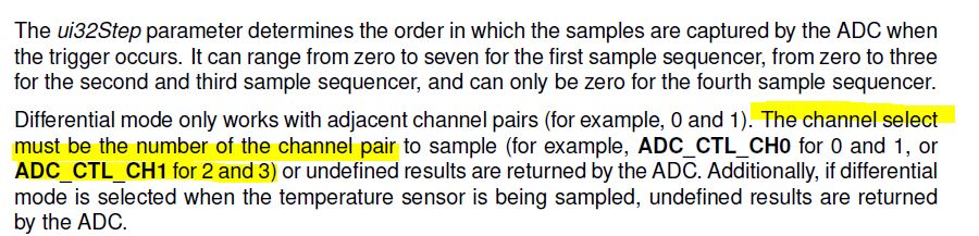
Whatever the voltage i am applying on AIN0 I am getting the same voltage but when I am doing the same connection on channel 2 and channel 3 then its not working

PE1-AIN2----connected to external voltage

PE0-AIN3----shorted with launchpad GND

Below code I have tried once go through it and let me know if I am doing any wrong

void DifferentialADCInit()
{

SysCtlPeripheralEnable(SYSCTL_PERIPH_ADC0);

SysCtlPeripheralEnable(SYSCTL_PERIPH_GPIOD);

GPIOPinTypeADC(GPIO_PORTD_BASE, GPIO_PIN_6 | GPIO_PIN_7); 

ADCSequenceConfigure(ADC0_BASE, 3, ADC_TRIGGER_PROCESSOR, 0);

ADCSequenceStepConfigure(ADC0_BASE, 3, 0, ADC_CTL_CH2  |  ADC_CTL_D | ADC_CTL_IE | ADC_CTL_END);

ADCSequenceEnable(ADC0_BASE, 3);

}

void DifferentialADCRead()
{


ADCIntClear(ADC0_BASE,3);
ADCProcessorTrigger(ADC0_BASE,3);
while(!ADCIntStatus(ADC0_BASE, 3,false));
ADCSequenceDataGet(ADC0_BASE, 3,Diff_Read);

diff_out1 = ((Diff_Read[0]-2048)*3.3)/2048.0;

}

int main(void)
{
ui32SysClock = SysCtlClockFreqSet((SYSCTL_XTAL_25MHZ | SYSCTL_OSC_MAIN | SYSCTL_USE_PLL | SYSCTL_CFG_VCO_480), 120000000);
DifferentialADCInit();

while(1)
{
DifferentialADCRead();
SysCtlDelay(4000000);
}

}

  • Hi,

      You wrote the below code to configure PD6 and PD7 for ADC. The PD6 and PD7 corresponds to AIN5 and AIN4. If you want to use AIN2 and AIN3 then you need to change to PE1 and PE0. 

    SysCtlPeripheralEnable(SYSCTL_PERIPH_GPIOD);

    GPIOPinTypeADC(GPIO_PORTD_BASE, GPIO_PIN_6 | GPIO_PIN_7); 

  • Hii Charles

    Thanks for your response. I did the same configuartion for Channel2 and Channel3 for differential mode

    PE1-AIN2----connected to external voltage

    PE0-AIN3----shorted with launchpad GND

    GPIOPinTypeADC(GPIO_PORTE_BASE, GPIO_PIN_1 | GPIO_PIN_0);

    and It did not work. Then I try to check on Channel4 and Channel 5(AIN4,AIN5) and it also not working.

    PD7-AIN4----connected to external voltage

    PD6-AIN5----shorted with launchpad GND

    Only AIN0 and AIN1 is working fine in differential mode.

    My requirement is  to read three adc channel in differential mode.

    Kindly suggest some sample code.

    Thanks & Regard

    Anamika

  • Hii Charles

    Sample code what I have tried is mentioned below once go through it for channel4 and channel5.And its not working

    PD7-AIN4----connected to external voltage

    PD6-AIN5----shorted with launchpad GND

    void DifferentialADCInit()
    {

    SysCtlPeripheralEnable(SYSCTL_PERIPH_ADC0);

    SysCtlPeripheralEnable(SYSCTL_PERIPH_GPIOD);

    GPIOPinTypeADC(GPIO_PORTD_BASE, GPIO_PIN_6 | GPIO_PIN_7); 

    ADCSequenceConfigure(ADC0_BASE, 3, ADC_TRIGGER_PROCESSOR, 0);

    ADCSequenceStepConfigure(ADC0_BASE, 3, 0, ADC_CTL_CH4  |  ADC_CTL_D | ADC_CTL_IE | ADC_CTL_END);

    ADCSequenceEnable(ADC0_BASE, 3);

    }

    void DifferentialADCRead()
    {


    ADCIntClear(ADC0_BASE,3);
    ADCProcessorTrigger(ADC0_BASE,3);
    while(!ADCIntStatus(ADC0_BASE, 3,false));
    ADCSequenceDataGet(ADC0_BASE, 3,Diff_Read);

    diff_out1 = ((Diff_Read[0]-2048)*3.3)/2048.0;

    }

    int main(void)
    {


    ui32SysClock = SysCtlClockFreqSet((SYSCTL_XTAL_25MHZ | SYSCTL_OSC_MAIN | SYSCTL_USE_PLL | SYSCTL_CFG_VCO_480), 120000000);
    DifferentialADCInit();

    while(1)
    {
    DifferentialADCRead();
    SysCtlDelay(4000000);
    }

    }

    Thanks & regard

    Anamika

  • Hi,

      When you are using differential mode, the ADC_CTL_CH1 denotes pair 1 which correspond to AIN2 and AIN3. If you want to use  AIN4 and AIN5, you will specify ADC_CTL_CH2 as pair 2. You specify ADC_CTL_CH4 for pair 4 which corresponds to AIN8 and AIN9.

  • Hii Charles,

    Thanks for your response. By selecting the correct channel pair selection its working,

    Appreciate your suggestion.

    Thanks & regard

    Anamika