Part Number: TM4C123GH6PM
I am connecting the DAC084SO to the TIVA C series Launch pad using SPI protocol in SSI0.
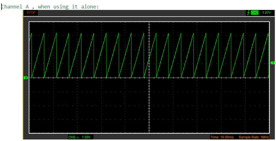
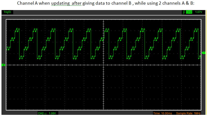
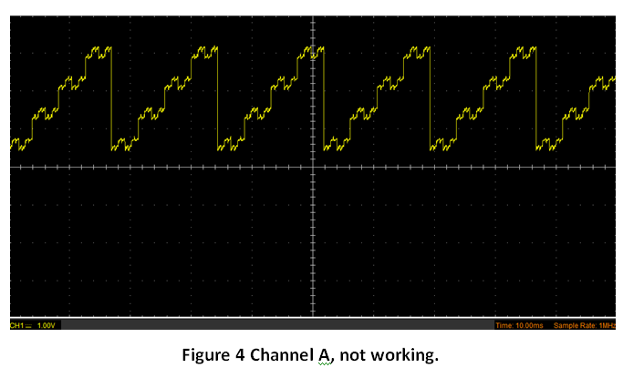
I write the same input values (a triangular wave form using the while loop with counter) to all 4 channels and I am getting the required output in the channels 2,3 and 4. However, I am getting disrupted output in output channel 1.
I have pasted the oscilloscope screen shots of the 3 working outputs and the 1 disrupted output below:

I have pasted the code below:
#include <stdbool.h>
#include <stdint.h>
#include "inc/hw_memmap.h"
#include "driverlib/gpio.h"
#include "driverlib/pin_map.h"
#include "driverlib/ssi.h"
#include "driverlib/sysctl.h"
#include "driverlib/uart.h"
#include "utils/uartstdio.h"

//*****************************************************************************
//! Trying to get DAC SSI 084 working. 4 channel.
//!
//! This example uses the following peripherals and I/O signals.  You must
//! review these and change as needed for your own board:
//! - SSI0 peripheral
//! - GPIO Port A peripheral (for SSI0 pins)
//! - SSI0Clk - PA2
//! - SSI0Fss - PA3
//! - SSI0Rx  - PA4
//! - SSI0Tx  - PA5
#define NUM_SSI_DATA            3

int
main(void)
{

    uint8_t loopCount = 0;
    uint16_t dacAaddress_dontUpdate = 0b0000;// Writing to regster 00 A , not updating till D is written
    uint16_t dacBaddress_dontUpdate = 0b0100;// Writing to regster 01 B,  not updating till D is written
    uint16_t dacCaddress_dontUpdate = 0b1000;// Writing to regster 10 C,  not updating till D is written
    uint16_t dacDaddress_doUpdate   = 0b1101;// Writing to regster 11 D,  updating all outputs as D is written

    // Shift the address and update bits 8 bits inside so that you can use OR operator to write the last 8 bits
    dacAaddress_dontUpdate = dacAaddress_dontUpdate<<8;
    dacBaddress_dontUpdate = dacBaddress_dontUpdate<<8;
    dacCaddress_dontUpdate = dacCaddress_dontUpdate<<8;
    dacDaddress_doUpdate   = dacDaddress_doUpdate<<8;

    SysCtlClockSet(SYSCTL_SYSDIV_1 | SYSCTL_USE_OSC | SYSCTL_OSC_MAIN | SYSCTL_XTAL_16MHZ);

    // The SSI0 peripheral must be enabled for use.
    SysCtlPeripheralEnable(SYSCTL_PERIPH_SSI0);

    // For this example SSI0 is used with PortA[5:2].
    SysCtlPeripheralEnable(SYSCTL_PERIPH_GPIOA);

    // Configure the pin muxing for SSI0 functions on port A2, A3, A4, and A5.
    GPIOPinConfigure(GPIO_PA2_SSI0CLK);
    GPIOPinConfigure(GPIO_PA3_SSI0FSS);
    GPIOPinConfigure(GPIO_PA4_SSI0RX);
    GPIOPinConfigure(GPIO_PA5_SSI0TX);

    // Configure the GPIO settings for the SSI pins.  This function also gives
    // control of these pins to the SSI hardware.  Consult the data sheet to
    // see which functions are allocated per pin.
    // The pins are assigned as follows:
    //      PA5 - SSI0Tx
    //      PA4 - SSI0Rx
    //      PA3 - SSI0Fss
    //      PA2 - SSI0CLK
    GPIOPinTypeSSI(GPIO_PORTA_BASE, GPIO_PIN_5 | GPIO_PIN_4 | GPIO_PIN_3 |GPIO_PIN_2);

    // Configure and enable the SSI port for TI master mode.  Use SSI0, system
    // clock supply, master mode, 1MHz SSI frequency, and 16-bit data.
    // Bit rate has to be 2MHz or higher
    SSIConfigSetExpClk(SSI0_BASE, SysCtlClockGet(), SSI_FRF_TI,SSI_MODE_MASTER, 1000000, 16);

    // Enable the SSI0 module.
    SSIEnable(SSI0_BASE);


    while(1){
        // Now use OR operator to put your control value in the input bits
        // Loop count is a 8 bit value . So will modify the last 8 bits of parent only.

        // Now shift  all the input variables to 4 bits inside further.
        // Input variable to the DAC048S is 16 bit and last 4 bits are expected to be useless.
        // Without shifting inside , the last 8 bits of the now 12 bit word will be neglected!.


        SSIDataPut(SSI0_BASE,  ((dacAaddress_dontUpdate | loopCount)<<4));
        SSIDataPut(SSI0_BASE,  ((dacBaddress_dontUpdate | loopCount)<<4));
        SSIDataPut(SSI0_BASE,  ((dacCaddress_dontUpdate | loopCount)<<4));
        SSIDataPut(SSI0_BASE,  ((dacDaddress_doUpdate   | loopCount)<<4));

        while(SSIBusy(SSI0_BASE)){}


        loopCount++;
        if (loopCount==255)
            loopCount=0;
    }

}
// UART interrupt handler, definition in main program
// Simply because we put this in NVIC table in startup ccs file, something has to be here.
void UARTIntHandler(void)
{
}
Any help on why one channel is not working smoothly?