This thread has been locked.

If you have a related question, please click the "Ask a related question" button in the top right corner. The newly created question will be automatically linked to this question.

Compiler/EK-TM4C123GXL: I WANT TO MAKE SQUARE WAVE THAT WAS ORIGINALLY HEART PULSE SENSOR'S ANALOG SIGNAL.

Part Number: EK-TM4C123GXL

Tool/software: TI C/C++ Compiler

Hi! I'm sungmin

The thing that I want to do is

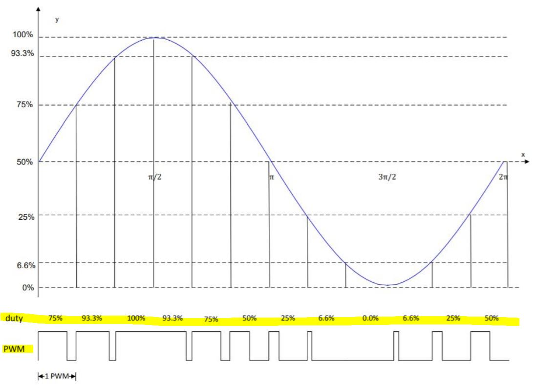
If my blood pressure signal goes into any Pin(for example, PE2), The output signal's form should be square waveform.

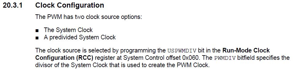
So, I tried PWM because the only thing that i remember was PWM.

BUT, PWM produces a square wave even if there is no input in the kit.

So, I tried to find another way.

that is 

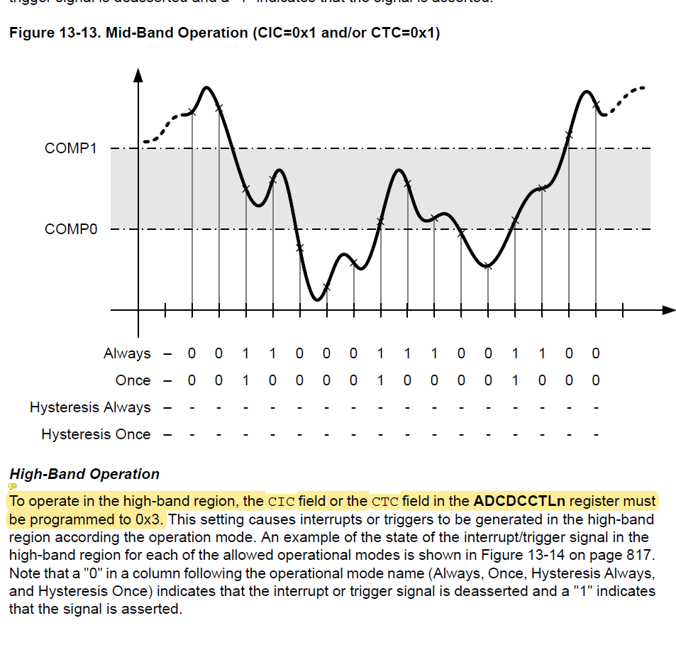
I thought thati could do it with 'Always-Mode' and 'high-band operation' with the same values of COMP1 and COMP0, 

BUT, I am not sure if this is correct.

I have no one who can teach me.

please help me :( ....

I really want to put the pulse sensor output value in TM4C so that the output comes out as a sqaure wave.

and i know the thing

I am certain that the pulse sensor signal is sampled using ADC.

  • Hi,

      You are missing the image. Can you upload the image again?

       What is your blood pressure signal? Is it a digital signal or a analog signal? From your description, it doesn't seem like you care care to know the input voltage. If the signal is a digital input, why don't use just use GPIO mode? In GPIO mode, you can configure to detect an edge on the signal input. If the edge is detected, you can start the PWM. Another question is if you need the PWM to continuously running or just one pulse? If you just need one pulse rather than PWM continuously then you might just want to use another GPIO pin to simply toggle the pin whenever an edge is detected on your input. I'm not entirely clear on what you want to do and hence all the questions asked. 


  • ok It seems that my English was poor and I could not communicate properly.

    What I just want is to represent the pulse signal, which is an analog signal, as a square wave using some method.

    So one of the methods I've been looking for is this picture (high-band-operation.).

    This may not be correct because it is just my thought

    After this method used ADC to sample, I saw that the sampling value is 1,0 according to COMP.

    So I thought that the values of 1,0 would be output as a square waveform.

    If it is not correct, please comment. ;(

    and If it is not, is there any way to make the output of the analog pulse sensor go into the kit's input so that the kit's output is in the form of a square wave?

    and if you cannot see my picture, i suggest that you can see the picture where it is located 'TM4C123GXL's DATASHEET - 816p'

  • I'm sorry that I posted the wrong PIC.

    the PIC is MID-BAND-OPERATION.

    but what I want to say is 'HIGH-BAND-OPERATION.'

  • https://e2e.ti.com/support/microcontrollers/other/f/908/t/678508

    The first answer's picture from the above address is what i wanted.

    you know I don't know entirely how to put coding to get it out like that.

    Is there any EXAMPLE CODE?..

    please help me

  • Hi,

      Let me try to understand exactly what you are trying to achieve. You want to generate the PWM signal in the below picture. Is that correct? The PWM shown in the waveform has a variable duty cycle. The MCU will output this variable duty cycle PWM. You will then connect this PWM output to a low pass filter (this will be an external component) and the sine wave will appear. 

      If you want to create a variable duty cycle PWM then you just need to change the duty cycle on each compare match. If you look at the diagram, you will start with a 75% duty cycle followed by a 93.3% duty cycle and 100%->93%->75%->50%.....

      To generate a PWM you will use the PWM module or the GPTM (timer) module in PWM mode. Take a look at the pwm_interrupt example in <TivaWare_Installation>/examples/boards/ek-tm4c123gxl/pwm_interrupt to see how the duty cycle is changed in the interrupt. Connect the PWM pin to a scope and see the waveform change. If you have a low-pass filter then connect the PWM pin through it and observe the filter output. Once you understand how it works, then you can change the code to adjust to whatever waveforms you want to create. 

  • yeah I want to output a sqaure wave is correct.

    'but' The input signals should be and could be any analog signals

    for example the input analog signal could be pulse sensor's signal.

    I think what you said is 'Just output the square wave when no input signal is applied to the TM4C123GXL'


    I want to do

    1. output the square wave when any analog input signal is applied.

    2. Then, how can I sample the analog signal in 12 bits?

    3. if I do, I am curious about how to output square wave through PWM for each bit.

    4. Lastly, I couldn't find ' <TivaWare_Installation> / examples / boards / ek-tm4c123gxl / pwm_interrupt ' that you sent

        is that homepage address? or built-in file?

       If it's the latter, I don't have that file on my computer. I wonder where to download.

  • First of all you can find the pwm_interrupt example as show below. There are also other examples like pwm_invert you can play with. The example is part of the TivaWare library. If you have not downloaded the TivaWare you can download from https://www.ti.com/tool/SW-TM4C. You can also find ADC examples in C:/ti/TivaWare_C_Series-2.2.0.295/examples/peripherals/adc folder. Run the ADC example to have an idea on how the ADC samples the input and convert it to a 12-bit digital value. 

    If I understand you correctly, you want to digitize an analog input. Is that correct? I can give you a high level idea. You need to work out the details. I will suggest you discuss with your professor and friends for your project. If you want to digitize an analog input then you can take the converted ADC input and find its percentage with respect to the reference voltage (3.3V). Use that percentage as your duty cycle for your PWM generation. Say for example, you sample an analog input of 1.65V. The 1.65V is converted by the ADC to a digital value of 2047. The 2047 is 50% of the reference voltage. Note that 3.3V input will be converted to 4095 so 1.65V is converted to 2047 for 50%. You will then apply 50% duty cycle to your PWM generation. Your PWM period will determine your ADC sampling frequency. Say your PWM period is 1.25uS or 800kHz. 800kHz will be how fast your can sample your analog input. You need to find out what is right for your application. 

  • yeah! I think maybe it will be correct soltuion.

    I tried to discuss with my professor and friends hardly.

    and tried so many googling.

    Nothing comes out of sampling the input and converting the result to a digital value and then outputting it.

    during 5 weeks I found out that I couldn't do it with my own ability to write the code myself.

    Is there a homepage with examples or a website worth a reference?

    I don't know how to implement the code.


    Most of the code implementation descriptions were related to the color of the diode.

    T.T  ....

    I'm really sorry to keep asking.

    Sadly, Nobody around me is good at handling 'CCS'

    http://users.ece.utexas.edu/~valvano/arm/#Timer

    There are many examples on this website, but it doesn't seem to have anything to do with what i'm tring to do.

    Is there any other website that have CCS examples?

    It's really hard to try CCS for the first time in this project.

    please help me T.T

    I am waiting for your reply every day and I feel very thankful.

  • HI,


    sungmin yoon said:
    Is there any other website that have CCS examples?

    Here is a link to the CCS training. 

    https://training.ti.com/getting-started-code-composer-studio-v7

    Here is a workshop for TM4C123 which also go through CCS training and examples on TM4C123. 

    https://processors.wiki.ti.com/index.php/Getting_Started_with_the_TIVA%E2%84%A2_C_Series_TM4C123G_LaunchPad

    sungmin yoon said:

    http://users.ece.utexas.edu/~valvano/arm/#Timer

    There are many examples on this website, but it doesn't seem to have anything to do with what i'm tring to do.

    Sorry, this is a University of Texas school course. We cannot support their class. You just need to learn it on your own. 

    sungmin yoon said:

    I tried to discuss with my professor and friends hardly.

    and tried so many googling.

    Nothing comes out of sampling the input and converting the result to a digital value and then outputting it.

    during 5 weeks I found out that I couldn't do it with my own ability to write the code myself.

    As much as I want to help you, I cannot write your project. I believe I have given you everything I can. Did you even try the examples that I ask you, the pwm_invert/pwm_interrupt and single_ended.c for ADC? The pwm_invert example shows you how to generate a PWM. The pwm_interrupt shows you how to change the duty cycle dynamically. The single_ended.c example shows you how to sample one ADC channel. You just need to combine these examples. I have also explained you the algorithm to digitize your input and output it on the PWM. I just cannot write your project as that is your responsibility. Sorry I cannot offer any more help. 

  • Thanks to your help, I succeeded in sampling and outputting PWM.

    But It did not happen when I tried to combine the two codes.

    Below thing is my code

    #include <stdbool.h>
    #include <stdint.h>
    #include "inc/hw_memmap.h"
    #include "driverlib/adc.h"
    #include "driverlib/debug.h"
    #include "driverlib/gpio.h"
    #include "driverlib/pin_map.h"
    #include "driverlib/pwm.h"
    #include "driverlib/rom.h"
    #include "driverlib/rom_map.h"
    #include "driverlib/sysctl.h"
    #include "driverlib/uart.h"
    #include "utils/uartstdio.h"

    void
    InitConsole(void)
    {

    SysCtlPeripheralEnable(SYSCTL_PERIPH_GPIOA);

    GPIOPinConfigure(GPIO_PA0_U0RX);
    GPIOPinConfigure(GPIO_PA1_U0TX);

    SysCtlPeripheralEnable(SYSCTL_PERIPH_UART0);

    UARTClockSourceSet(UART0_BASE, UART_CLOCK_PIOSC);

    GPIOPinTypeUART(GPIO_PORTA_BASE, GPIO_PIN_0 | GPIO_PIN_1);

    UARTStdioConfig(0, 115200, 16000000);
    }

    #ifdef DEBUG
    void
    __error__(char *pcFilename, uint32_t ui32Line)
    {
    }
    #endif
    void
    ConfigureUART(void)
    {

    MAP_SysCtlPeripheralEnable(SYSCTL_PERIPH_GPIOA);

    MAP_SysCtlPeripheralEnable(SYSCTL_PERIPH_UART0);

    MAP_GPIOPinConfigure(GPIO_PA0_U0RX);
    MAP_GPIOPinConfigure(GPIO_PA1_U0TX);
    MAP_GPIOPinTypeUART(GPIO_PORTA_BASE, GPIO_PIN_0 | GPIO_PIN_1);

    UARTClockSourceSet(UART0_BASE, UART_CLOCK_PIOSC);

    UARTStdioConfig(0, 115200, 16000000);
    }

    int
    main(void)
    {
    #if defined(TARGET_IS_TM4C129_RA0) || \
    defined(TARGET_IS_TM4C129_RA1) || \
    defined(TARGET_IS_TM4C129_RA2)
    uint32_t ui32SysClock;
    #endif

    uint32_t pui32ADC0Value[1];

    #if defined(TARGET_IS_TM4C129_RA0) || \
    defined(TARGET_IS_TM4C129_RA1) || \
    defined(TARGET_IS_TM4C129_RA2)
    //
    // Note: SYSCTL_CFG_VCO_240 is a new setting provided in TivaWare 2.2.x and
    // later to better reflect the actual VCO speed due to SYSCTL#22.
    //
    ui32SysClock = SysCtlClockFreqSet((SYSCTL_XTAL_25MHZ |
    SYSCTL_OSC_MAIN |
    SYSCTL_USE_PLL |
    SYSCTL_CFG_VCO_240), 20000000);
    #else
    SysCtlClockSet(SYSCTL_SYSDIV_10 | SYSCTL_USE_PLL | SYSCTL_OSC_MAIN |
    SYSCTL_XTAL_16MHZ);
    #endif

    InitConsole();

    UARTprintf("ADC ->\n");
    UARTprintf(" Type: Single Ended\n");
    UARTprintf(" Samples: One\n");
    UARTprintf(" Update Rate: 250ms\n");
    UARTprintf(" Input Pin: AIN0/PE3\n\n");

    SysCtlPeripheralEnable(SYSCTL_PERIPH_ADC0);

    SysCtlPeripheralEnable(SYSCTL_PERIPH_GPIOE);

    GPIOPinTypeADC(GPIO_PORTE_BASE, GPIO_PIN_3);

    ADCSequenceConfigure(ADC0_BASE, 3, ADC_TRIGGER_PROCESSOR, 0);

    ADCSequenceStepConfigure(ADC0_BASE, 3, 0, ADC_CTL_CH0 | ADC_CTL_IE |
    ADC_CTL_END);

    ADCSequenceEnable(ADC0_BASE, 3);

    ADCIntClear(ADC0_BASE, 3);

    while(1)
    {

    ADCProcessorTrigger(ADC0_BASE, 3);

    while(!ADCIntStatus(ADC0_BASE, 3, false))
    {
    }
    ADCIntClear(ADC0_BASE, 3);

    ADCSequenceDataGet(ADC0_BASE, 3, pui32ADC0Value);

    UARTprintf("AIN0 = %d\n", pui32ADC0Value[0]);

    #if defined(TARGET_IS_TM4C129_RA0) || \
    defined(TARGET_IS_TM4C129_RA1) || \
    defined(TARGET_IS_TM4C129_RA2)
    SysCtlDelay(ui32SysClock / 12);
    #else
    SysCtlDelay(SysCtlClockGet() / 12);
    #endif
    MAP_SysCtlClockSet(SYSCTL_SYSDIV_1 | SYSCTL_USE_OSC | SYSCTL_OSC_MAIN |
    SYSCTL_XTAL_16MHZ);
    MAP_SysCtlPWMClockSet(SYSCTL_PWMDIV_1);

    MAP_SysCtlPeripheralEnable(SYSCTL_PERIPH_PWM0);

    MAP_SysCtlPeripheralEnable(SYSCTL_PERIPH_GPIOB);

    MAP_GPIOPinConfigure(GPIO_PB6_M0PWM0);
    MAP_GPIOPinTypePWM(GPIO_PORTB_BASE, GPIO_PIN_6);

    MAP_PWMGenConfigure(PWM0_BASE, PWM_GEN_0, PWM_GEN_MODE_UP_DOWN |
    PWM_GEN_MODE_NO_SYNC);


    MAP_PWMGenPeriodSet(PWM0_BASE, PWM_GEN_0, (SysCtlClockGet() / 250));

    MAP_PWMPulseWidthSet(PWM0_BASE, PWM_OUT_0,
    MAP_PWMGenPeriodGet(PWM0_BASE, PWM_GEN_0) / 4); // I want to put pui32ADC0Value[0]/4000 where 4 is here

    MAP_PWMOutputState(PWM0_BASE, PWM_OUT_0_BIT, true);

    MAP_PWMGenEnable(PWM0_BASE, PWM_GEN_0);

    }
    }

    The first problem I am curious about is that when there is only ADC in the while, it repeats normally, but if I put the pwm code together in 'while{1}', it works only once.

    I thought it would be possible to express the ADC value in percent where the PWM's period is set

    (MAP_PWMGenPeriodGet(PWM0_BASE, PWM_GEN_0) / 4); // I want to put pui32ADC0Value[0]/4000 where 4 is here) <<<

    However, it was executed only once in the loop and ended, so there was no output.

    How can I solve this problem?

  • First of all, when pasting your code, click the icon shown (highlighted in yellow) below to enter your code. Don't paste your code like what you have right now. It is very hard to read without indentation. 

    Why are you putting the entire PWM configuration in the while loop? You are calling every line of the PWM configuration each time you are repeating the loop, isn't? You should move the code outside the loop and only keep the MAP_PWMPulseWidthSet() inside the loop if you want to change the duty cycle.

    #if defined(TARGET_IS_TM4C129_RA0) || \
    defined(TARGET_IS_TM4C129_RA1) || \
    defined(TARGET_IS_TM4C129_RA2)
    SysCtlDelay(ui32SysClock / 12);
    #else
    SysCtlDelay(SysCtlClockGet() / 12);
    #endif
    MAP_SysCtlClockSet(SYSCTL_SYSDIV_1 | SYSCTL_USE_OSC | SYSCTL_OSC_MAIN |
    SYSCTL_XTAL_16MHZ);
    MAP_SysCtlPWMClockSet(SYSCTL_PWMDIV_1);
    
    MAP_SysCtlPeripheralEnable(SYSCTL_PERIPH_PWM0);
    
    MAP_SysCtlPeripheralEnable(SYSCTL_PERIPH_GPIOB);
    
    MAP_GPIOPinConfigure(GPIO_PB6_M0PWM0);
    MAP_GPIOPinTypePWM(GPIO_PORTB_BASE, GPIO_PIN_6);
    
    MAP_PWMGenConfigure(PWM0_BASE, PWM_GEN_0, PWM_GEN_MODE_UP_DOWN |
    PWM_GEN_MODE_NO_SYNC);
    
    
    MAP_PWMGenPeriodSet(PWM0_BASE, PWM_GEN_0, (SysCtlClockGet() / 250));
    
    MAP_PWMPulseWidthSet(PWM0_BASE, PWM_OUT_0,
    MAP_PWMGenPeriodGet(PWM0_BASE, PWM_GEN_0) / 4); // I want to put pui32ADC0Value[0]/4000 where 4 is here
    
    MAP_PWMOutputState(PWM0_BASE, PWM_OUT_0_BIT, true);
    
    MAP_PWMGenEnable(PWM0_BASE, PWM_GEN_0);

  • Thanks to your help, I confirmed that the ADC keeps outputting.

    but there is another problem which is '

    MAP_PWMPulseWidthSet(PWM0_BASE, PWM_OUT_0,
    MAP_PWMGenPeriodGet(PWM0_BASE, PWM_GEN_0) *((pui32ADC0Value[0])/4095))

    I thought that if I do that, the square wave will be output because the value that is 'pui32ADCValue[0]/4095' comes out in percent form.

    BUT, the output waveform was a strange waveform.

    The cause I thought is 

     ADC comes out very fast, the frequency of sqaure wave generation is 250HZ and the input signal's frequency is almost 1.5HZ BECAUSE it's my blood pulse.

    So, to solve this problem, I tried to change the PWM's output frequency 

    but I could not make 1.5hz 

    like this MAP_PWMGenPeriodSet(PWM0_BASE, PWM_GEN_0, (SysCtlClockGet() / 1.5));

    I do not think I'm sure the problem I've guessed.

    What problem do I have to solve to make a square wave according to the changing input's ADC value

    below code that I wrote

    Thanks for continuing to answer. I've never seen like anyone as kind as you


    #include <stdbool.h>
    #include <stdint.h>
    #include "inc/hw_memmap.h"
    #include "driverlib/adc.h"
    #include "driverlib/debug.h"
    #include "driverlib/gpio.h"
    #include "driverlib/pin_map.h"
    #include "driverlib/pwm.h"
    #include "driverlib/rom.h"
    #include "driverlib/rom_map.h"
    #include "driverlib/sysctl.h"
    #include "driverlib/uart.h"
    #include "utils/uartstdio.h"
    
    void
    InitConsole(void)
    {
    
        SysCtlPeripheralEnable(SYSCTL_PERIPH_GPIOA);
    
        GPIOPinConfigure(GPIO_PA0_U0RX);
        GPIOPinConfigure(GPIO_PA1_U0TX);
    
        SysCtlPeripheralEnable(SYSCTL_PERIPH_UART0);
    
        UARTClockSourceSet(UART0_BASE, UART_CLOCK_PIOSC);
    
        GPIOPinTypeUART(GPIO_PORTA_BASE, GPIO_PIN_0 | GPIO_PIN_1);
    
        UARTStdioConfig(0, 115200, 16000000);
    }
    
    #ifdef DEBUG
    void
    __error__(char *pcFilename, uint32_t ui32Line)
    {
    }
    #endif
    void
    ConfigureUART(void)
    {
    
        MAP_SysCtlPeripheralEnable(SYSCTL_PERIPH_GPIOA);
    
        MAP_SysCtlPeripheralEnable(SYSCTL_PERIPH_UART0);
    
        MAP_GPIOPinConfigure(GPIO_PA0_U0RX);
        MAP_GPIOPinConfigure(GPIO_PA1_U0TX);
        MAP_GPIOPinTypeUART(GPIO_PORTA_BASE, GPIO_PIN_0 | GPIO_PIN_1);
    
        UARTClockSourceSet(UART0_BASE, UART_CLOCK_PIOSC);
    
        UARTStdioConfig(0, 115200, 16000000);
    }
    
    int
    main(void)
    {
        MAP_SysCtlClockSet(SYSCTL_SYSDIV_1 | SYSCTL_USE_OSC | SYSCTL_OSC_MAIN |
        SYSCTL_XTAL_16MHZ);
        MAP_SysCtlPWMClockSet(SYSCTL_PWMDIV_1);
    
        MAP_SysCtlPeripheralEnable(SYSCTL_PERIPH_PWM0);
    
        MAP_SysCtlPeripheralEnable(SYSCTL_PERIPH_GPIOB);
    
        MAP_GPIOPinConfigure(GPIO_PB6_M0PWM0);
        MAP_GPIOPinTypePWM(GPIO_PORTB_BASE, GPIO_PIN_6);
    
        MAP_PWMGenConfigure(PWM0_BASE, PWM_GEN_0, PWM_GEN_MODE_UP_DOWN |
        PWM_GEN_MODE_NO_SYNC);
    
    
        MAP_PWMGenPeriodSet(PWM0_BASE, PWM_GEN_0, (SysCtlClockGet() / 250));
    
        MAP_PWMOutputState(PWM0_BASE, PWM_OUT_0_BIT, true);
    
        MAP_PWMGenEnable(PWM0_BASE, PWM_GEN_0);
    #if defined(TARGET_IS_TM4C129_RA0) ||                                         \
            defined(TARGET_IS_TM4C129_RA1) ||                                         \
            defined(TARGET_IS_TM4C129_RA2)
        uint32_t ui32SysClock;
    #endif
    
        uint32_t pui32ADC0Value[1];
    
    #if defined(TARGET_IS_TM4C129_RA0) ||                                         \
            defined(TARGET_IS_TM4C129_RA1) ||                                         \
            defined(TARGET_IS_TM4C129_RA2)
        //
        // Note: SYSCTL_CFG_VCO_240 is a new setting provided in TivaWare 2.2.x and
        // later to better reflect the actual VCO speed due to SYSCTL#22.
        //
        ui32SysClock = SysCtlClockFreqSet((SYSCTL_XTAL_25MHZ |
                SYSCTL_OSC_MAIN |
                SYSCTL_USE_PLL |
                SYSCTL_CFG_VCO_240), 20000000);
    #else
        SysCtlClockSet(SYSCTL_SYSDIV_10 | SYSCTL_USE_PLL | SYSCTL_OSC_MAIN |
                       SYSCTL_XTAL_16MHZ);
    #endif
    
        InitConsole();
    
        UARTprintf("ADC ->\n");
        UARTprintf("  Type: Single Ended\n");
        UARTprintf("  Samples: One\n");
        UARTprintf("  Update Rate: 250ms\n");
        UARTprintf("  Input Pin: AIN0/PE3\n\n");
    
        SysCtlPeripheralEnable(SYSCTL_PERIPH_ADC0);
    
        SysCtlPeripheralEnable(SYSCTL_PERIPH_GPIOE);
    
        GPIOPinTypeADC(GPIO_PORTE_BASE, GPIO_PIN_3);
    
        ADCSequenceConfigure(ADC0_BASE, 3, ADC_TRIGGER_PROCESSOR, 0);
    
        ADCSequenceStepConfigure(ADC0_BASE, 3, 0, ADC_CTL_CH0 | ADC_CTL_IE |
                                 ADC_CTL_END);
    
        ADCSequenceEnable(ADC0_BASE, 3);
    
        ADCIntClear(ADC0_BASE, 3);
    
    
        while(1)
        {
    
            ADCProcessorTrigger(ADC0_BASE, 3);
    
            while(!ADCIntStatus(ADC0_BASE, 3, false))
            {
            }
            ADCIntClear(ADC0_BASE, 3);
    
            ADCSequenceDataGet(ADC0_BASE, 3, pui32ADC0Value);
    
            UARTprintf("AIN0 = %d\n", pui32ADC0Value[0]);
            SysCtlDelay(1000000);
    
            MAP_PWMPulseWidthSet(PWM0_BASE, PWM_OUT_0,
            MAP_PWMGenPeriodGet(PWM0_BASE, PWM_GEN_0) *((pui32ADC0Value[0])/4095)); // pui32ADC0Value[0]/4095 means duty cycle
    
    
        }
    }
    

  • Hi,

      The PWM counter is only 16bit. It looks like your SYSCLK is 20Mhz per your clock configuration as follows.

    SysCtlClockSet(SYSCTL_SYSDIV_10 | SYSCTL_USE_PLL | SYSCTL_OSC_MAIN |
                       SYSCTL_XTAL_16MHZ);

    Therefore, the SysCtlClockGet() / 1.5) will be 20000000/1.5=13333333. This is a value that is larger than the the 16-bit counter can store. You can slow down your timebase by either slowing down SYSCLK or increase the divider for the PWM clock. To slow down the SYSCLK you can change from SYSCTL_SYSDIV_10 (this is what you currently have) to something slower. You can further slow down the PWM clock by dividing the SYSCLK using MAP_SysCtlPWMClockSet. You current use MAP_SysCtlPWMClockSet(SYSCTL_PWMDIV_1). You can slow this down further. You need to play with the clock to achieve your 1.5Hz requirement. 

    P.S. Note that you also have two clock configuration. Which one do you want. You can cause trouble when you have two of them  in your code. 

    MAP_SysCtlClockSet(SYSCTL_SYSDIV_1 | SYSCTL_USE_OSC | SYSCTL_OSC_MAIN |
        SYSCTL_XTAL_16MHZ);
        SysCtlClockSet(SYSCTL_SYSDIV_10 | SYSCTL_USE_PLL | SYSCTL_OSC_MAIN |
                       SYSCTL_XTAL_16MHZ);
  • last monday, I finally finished it for your help.

    suddenly I remember that if without your help, I have never finished my project

    Thank you So Much!!!

    :)

  • Glad your problem is solved. If you don't mind, please share your code with the community so someone might benefit.

  • #include <stdbool.h>
    #include <stdint.h>
    #include "inc/hw_memmap.h"
    #include "driverlib/adc.h"
    #include "driverlib/debug.h"
    #include "driverlib/gpio.h"
    #include "driverlib/pin_map.h"
    #include "driverlib/pwm.h"
    #include "driverlib/rom.h"
    #include "driverlib/rom_map.h"
    #include "driverlib/sysctl.h"
    #include "driverlib/uart.h"
    #include "utils/uartstdio.h"
    
    void
    InitConsole(void)
    {
    
        SysCtlPeripheralEnable(SYSCTL_PERIPH_GPIOA);
    
        GPIOPinConfigure(GPIO_PA0_U0RX);
        GPIOPinConfigure(GPIO_PA1_U0TX);
    
        SysCtlPeripheralEnable(SYSCTL_PERIPH_UART0);
    
        UARTClockSourceSet(UART0_BASE, UART_CLOCK_PIOSC);
    
        GPIOPinTypeUART(GPIO_PORTA_BASE, GPIO_PIN_0 | GPIO_PIN_1);
    
        UARTStdioConfig(0, 115200, 16000000);
    }
    
    #ifdef DEBUG
    void
    __error__(char *pcFilename, uint32_t ui32Line)
    {
    }
    #endif
    void
    ConfigureUART(void)
    {
    
        MAP_SysCtlPeripheralEnable(SYSCTL_PERIPH_GPIOA);
    
        MAP_SysCtlPeripheralEnable(SYSCTL_PERIPH_UART0);
    
        MAP_GPIOPinConfigure(GPIO_PA0_U0RX);
        MAP_GPIOPinConfigure(GPIO_PA1_U0TX);
        MAP_GPIOPinTypeUART(GPIO_PORTA_BASE, GPIO_PIN_0 | GPIO_PIN_1);
    
        UARTClockSourceSet(UART0_BASE, UART_CLOCK_PIOSC);
    
        UARTStdioConfig(0, 115200, 16000000);
    }
    
    int
    main(void)
    {
        float a;
        float b;
        MAP_SysCtlPWMClockSet(SYSCTL_PWMDIV_1);
    
        MAP_SysCtlPeripheralEnable(SYSCTL_PERIPH_PWM0);
    
        MAP_SysCtlPeripheralEnable(SYSCTL_PERIPH_GPIOB);
    
        MAP_GPIOPinConfigure(GPIO_PB6_M0PWM0);
        MAP_GPIOPinTypePWM(GPIO_PORTB_BASE, GPIO_PIN_6);
    
        MAP_PWMGenConfigure(PWM0_BASE, PWM_GEN_0, PWM_GEN_MODE_UP_DOWN |
        PWM_GEN_MODE_NO_SYNC);
    
    
        MAP_PWMGenPeriodSet(PWM0_BASE, PWM_GEN_0, (SysCtlClockGet() / 250));
    
        MAP_PWMOutputState(PWM0_BASE, PWM_OUT_0_BIT, true);
    
        MAP_PWMGenEnable(PWM0_BASE, PWM_GEN_0);
    #if defined(TARGET_IS_TM4C129_RA0) ||                                         \
            defined(TARGET_IS_TM4C129_RA1) ||                                         \
            defined(TARGET_IS_TM4C129_RA2)
        uint32_t ui32SysClock;
    #endif
    
        uint32_t pui32ADC0Value[1];
    
    #if defined(TARGET_IS_TM4C129_RA0) ||                                         \
            defined(TARGET_IS_TM4C129_RA1) ||                                         \
            defined(TARGET_IS_TM4C129_RA2)
        //
        // Note: SYSCTL_CFG_VCO_240 is a new setting provided in TivaWare 2.2.x and
        // later to better reflect the actual VCO speed due to SYSCTL#22.
        //
        ui32SysClock = SysCtlClockFreqSet((SYSCTL_XTAL_25MHZ |
                SYSCTL_OSC_MAIN |
                SYSCTL_USE_PLL |
                SYSCTL_CFG_VCO_240), 20000000);
    #else
        SysCtlClockSet(SYSCTL_SYSDIV_16 | SYSCTL_USE_PLL | SYSCTL_OSC_MAIN |
                       SYSCTL_XTAL_1MHZ);
    #endif
    
        InitConsole();
    
        UARTprintf("ADC ->\n");
        UARTprintf("  Type: Single Ended\n");
        UARTprintf("  Samples: One\n");
        UARTprintf("  Update Rate: 250ms\n");
        UARTprintf("  Input Pin: AIN0/PE3\n\n");
    
        SysCtlPeripheralEnable(SYSCTL_PERIPH_ADC0);
    
        SysCtlPeripheralEnable(SYSCTL_PERIPH_GPIOE);
    
        GPIOPinTypeADC(GPIO_PORTE_BASE, GPIO_PIN_3);
    
        ADCSequenceConfigure(ADC0_BASE, 3, ADC_TRIGGER_PROCESSOR, 0);
    
        ADCSequenceStepConfigure(ADC0_BASE, 3, 0, ADC_CTL_CH0 | ADC_CTL_IE |
                                 ADC_CTL_END);
    
        ADCSequenceEnable(ADC0_BASE, 3);
    
        ADCIntClear(ADC0_BASE, 3);
    
    
        while(1)
        {
    
            ADCProcessorTrigger(ADC0_BASE, 3);
    
            while(!ADCIntStatus(ADC0_BASE, 3, false))
            {
            }
            ADCIntClear(ADC0_BASE, 3);
    
            ADCSequenceDataGet(ADC0_BASE, 3, pui32ADC0Value);
    
            UARTprintf("AIN0 = %d\n", pui32ADC0Value[0]);
            SysCtlDelay(100000);
            a=pui32ADC0Value[0];
            b=a-1970;
            if (b>130)
                b=0.999908;
            else
                b=0;
    
            MAP_PWMPulseWidthSet(PWM0_BASE, PWM_OUT_0,
            MAP_PWMGenPeriodGet(PWM0_BASE, PWM_GEN_0) *b); // pui32ADC0Value[0]/4095 means duty cycle
    
    
        }
    }
    

    Thank you Sir !!