This thread has been locked.

If you have a related question, please click the "Ask a related question" button in the top right corner. The newly created question will be automatically linked to this question.

TM4C129XNCZAD: CANTST Tx:01 Sample Mode

Part Number: TM4C129XNCZAD

I have this device showing an ACK error when on a long cable (30m) and about 600 ns of total round trip delay from CANnTX to CANnRX.  With 15 quanta per 1 Mbps CAN I have the sample point set well past this, but I'm seeing intermittent operation (occasionally 600 ns will fail while 640 ns will pass). 

Tiva 120 MHz

Clocks/bit =         15

Predivide =            8

TSEG1                   13             

TSEG2                    1

SJW                        1

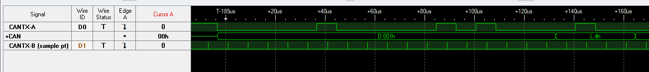
I want to verify the bit timing with the "Sample Point" mode (CANTST Tx:01), but after enabling this mode: 

Init CAN

Enable CAN

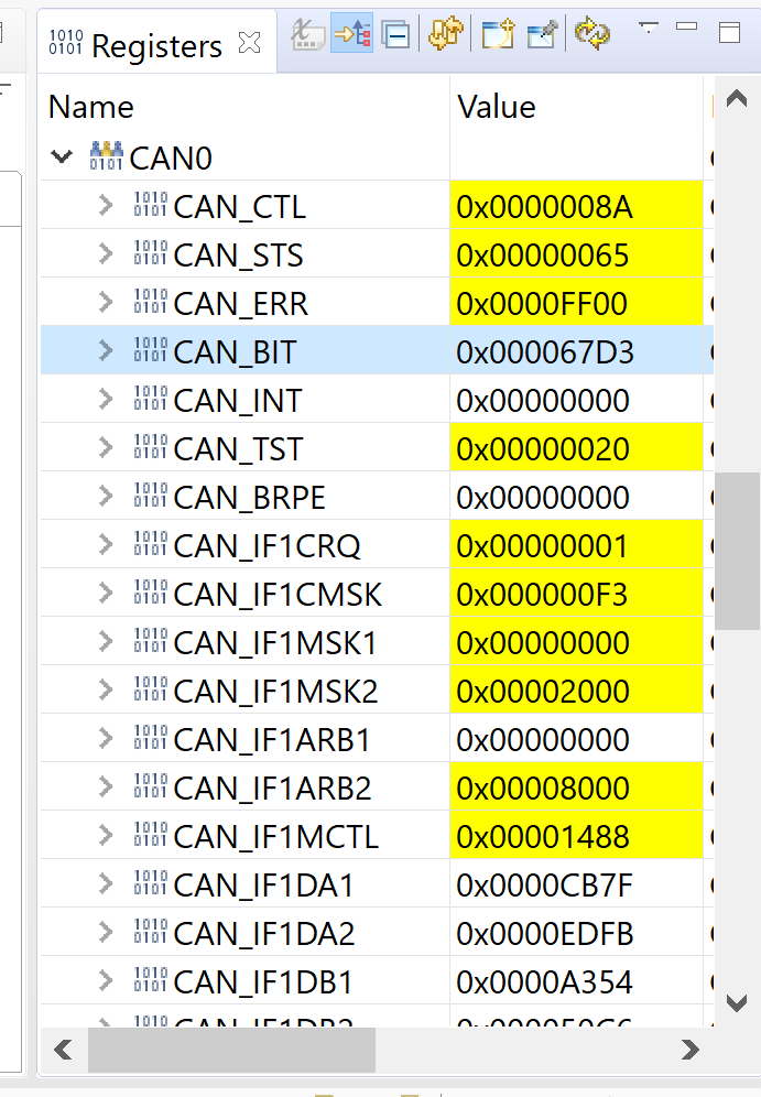
Set TST bit in CANCTL

Set CANTST:Tx to "01" for Sample Point

I am still only seeing typical CAN data on the Tx pin (ACK after receiving a CAN message, Normal bit stream when sending a message).  I'm expecting to see an edge per bit time at the Sample Point, but I'm not seeing that.  Is there more documentation on the "Sample Point" testing somewhere?  Or example code?  Do I need to disable some other CAN operation for the "Sample Point" test mode to take over? 

  • How did you put the CAN module in sample point mode? Here are the register writes that I used in a different project.

        // Put the CAN module in sample point mode
        HWREG(CAN0_BASE + CAN_O_CTL) |= 0x80u; //Enable test
        HWREG(CAN0_BASE + CAN_O_TST) = 0x20u;  //Enable sample point
    

    Here is the logic analyzer shot. In this project the baudrate is 125K and the sample point is centered. Also, the TX pin from node B is disconnected from the transceiver to avoid causing errors on the CAN bus.

  • Oops, wrong button, this isn't resolved yet. 

    That's about what I was expecting, except I'm surprised the sample pt is showing as a pulse and not an edge.  Can you zoom in on that to see how wide the sample pt pulse is?  Maybe I'm sampling too slow to capture it. 

  • That's not it.  I'm now sampling at 500 Msps and not seeing anyting, so this should even catch 120 MHz system clock pulses. 

  • The sample point signal is a positive pulse equal to the period of the system clock. In your case (120MHz) it is 8.3nS.. 

  • Thanks.  I'm still only seeing typical CAN traffic on the Tx pin.  Here's my full initialization sequence: 

    void InitializeCAN( uint8_t CANHardwareNumber,

                        uint32_t CANBase,

                        uint32_t CANBitRate,

                        uint32_t ReceiveFilter1,

                        uint32_t ReceiveFilter2,

                        uint32_t ReceiveFilter3,

                        uint32_t IDMask,

                        uint32_t SourceClock )

    {

        uint16_t ui16CANCTL;


        CANInit( CANBase );

        //for 120MHz clock

        tCANBitClkParms CANBitClkSettings = {13, 1, 1, 8};


        CANBitTimingSet(CANBase, &CANBitClkSettings);

    #endif


        {

            CANEnable( CANBase );


            //Set Test bit in control register, which write-enables test register.

            ui16CANCTL = HWREG(CANBase + CAN_O_CTL);

            HWREG(CANBase + CAN_O_CTL) = ui16CANCTL | CAN_CTL_TEST;


            //Enable sample point test

            HWREG(CANBase + CAN_O_TST) = CAN_TST_TX_SAMPLE;


            CANIntEnable( CANBase, CAN_INT_MASTER | CAN_INT_ERROR );


            /* Configure the receive message FIFO.          */

            CANReceiveFIFO( CANHardwareNumber, ReceiveFilter1, ReceiveFilter2, ReceiveFilter3, IDMask );


            if( CANHardwareNumber == CAN0_BUS )

            {

                IntEnable( INT_CAN0 );

            }

            else if( CANHardwareNumber == CAN1_BUS )

            {

                IntEnable( INT_CAN1 );

            }

            CANControl[CAN0_BUS].StatusControl = 0;

            CANControl[CAN1_BUS].StatusControl = 0;

        }

        CANSendingMonitorValues = 0;

        MonitorValuesRequestedBy = 0;


        CANLargePayloadLastSerialNumber = 0;


        MessageBackupToCANHardwareCounter[CAN0_BUS] = 0;

        MessageBackupToCANHardwareCounter[CAN1_BUS] = 0;

    }

    Is it possible that any of that additional setup is disabling the test mode? 

  • What is the purpose of these two lines? Are these mapped back to the hardware CAN control register? Can you provide a screen shot of the relevant CAN registers after running the initialization code?

          CANControl[CAN0_BUS].StatusControl = 0;
    
          CANControl[CAN1_BUS].StatusControl = 0;


    (Next time you want to insert code snippets in the thread, use the </> symbol from the menu bar. It will keep code formatting.)

  • Thanks Bob, for the tip on code snippets.  This will take some deeper digging next week.