This thread has been locked.

If you have a related question, please click the "Ask a related question" button in the top right corner. The newly created question will be automatically linked to this question.

TM4C1290NCPDT: Input impedance of ADC port

Part Number: TM4C1290NCPDT

Hi Team

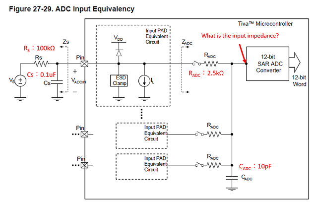
We are using the ADC port in the following circuit diagram and configuration.

Could you tell me about the questions below?

1. If the external capacitor Cs=0.1uF is attached, can I use the resistance of Rs=100kΩ?

2. What is the input impedance of the ADC Converter? 

Regards

  • Hello Kawa,

    Depends what sampling frequency you are going for. You want the signal at the ADC to be able to settle in time which is why there is lower Rs max values as the Ksps increases. If you are looking to run at the full ADC speed, that R/C filter would not work.

    You could consider having a unity gain op amp to help reduce the impedance if you need the 100kOhm.

    Also maybe this app note would help: https://www.ti.com/lit/an/sbaa108a/sbaa108a.pdf?ts=1601326062335&ref_url=https%253A%252F%252Fe2e.ti.com%252F

    Kawa said:
    2. What is the input impedance of the ADC Converter? 

    I don't believe we have a spec for the exact point indicated. The Radc and Cadc values provided should give you enough to characterize the internals of the system for your needs.

  • Hello  Jacobi,

    If Cs capacitor is sufficiently larger than CADC capacitor, I think the value of Rs is not involved in the R/C filter.
    So I think it's a no problem for the Rs resistance to be 100kΩ.
    Is this understanding mistaken?

    Best Regards,

  • Kawa,

    From the standpoint of charge sharing, you are correct. The external 0.1uF capacitor is 10000x the internal sample capacitance. Charge sharing would create an error of less than one least significant bit. However, you did not take into account the maximum input leakage of 2uA. (Perhaps this is what you were trying to ask when you asked about input impedance to the converter.) That worst case leakage (typical leakage will be less) can offset the voltage at your external capacitor by 0.2V (2uA x 100K Ohms). Also the 100K Ohm resistor with the 0.1uF capacitor will make the response time of your low pass filter very slow. You will not be able to detect rapid changes of the external voltage. (10Hz or slower should be OK. 100Hz or faster will be degraded.)

  • Hello  Crosby,

    I got it, thanks.

    Best Regards,