This thread has been locked.

If you have a related question, please click the "Ask a related question" button in the top right corner. The newly created question will be automatically linked to this question.

TM4C129DNCPDT: USB with reduced sysclk frequency

Part Number: TM4C129DNCPDT

We have a TIVA 129 configured with PLL frequency of 480MHz and system clock of 120 MHz.  To reduce power at certain times, we wish to reduce the sysclk to a much lower value, while keeping everything else (including USB) operational. During these times we know the I/O and processor load will be greatly reduced. 

Using USB on the TIVA as a CDC device.

The PLL remains at 480MHz, and we change SYSDIV and MEMTIM0 as indicated at the end of section 5.3 of the manual. This works as desired, and we see good power savings when changing from 120MHz to, for example, 30MHz, and everything is reliable.

We would like to go to a lower rate and save more power.  When dropping to, for example, 12MHz, the USB becomes unreliable.  (We are using the CDC device driver).  When entering chars from a terminal emulator at human entry rates, some characters from the terminal emulator are either not received or not echoed (the echo is our code, which is reliable at all rates). Also, when a char is dropped, the processor seems to be stuck somewhere in the usb driver (from TI).  The flashing LED indicates that the processor is still up and that interrupts continue to be serviced. 

Disconnecting (logically, not physically) and reconnecting the terminal emulator often shows some of the "stuck" output and response, and also indicates that some of the input characters were missed at times.  In this case, reconnecting shows the same device name under Linux, so we know that re-enumeration of devices on the bus has not occurred.  (Using coolTerm under Linux).

The tivaware usb library readme file indicates revision 2.1.0.12573.

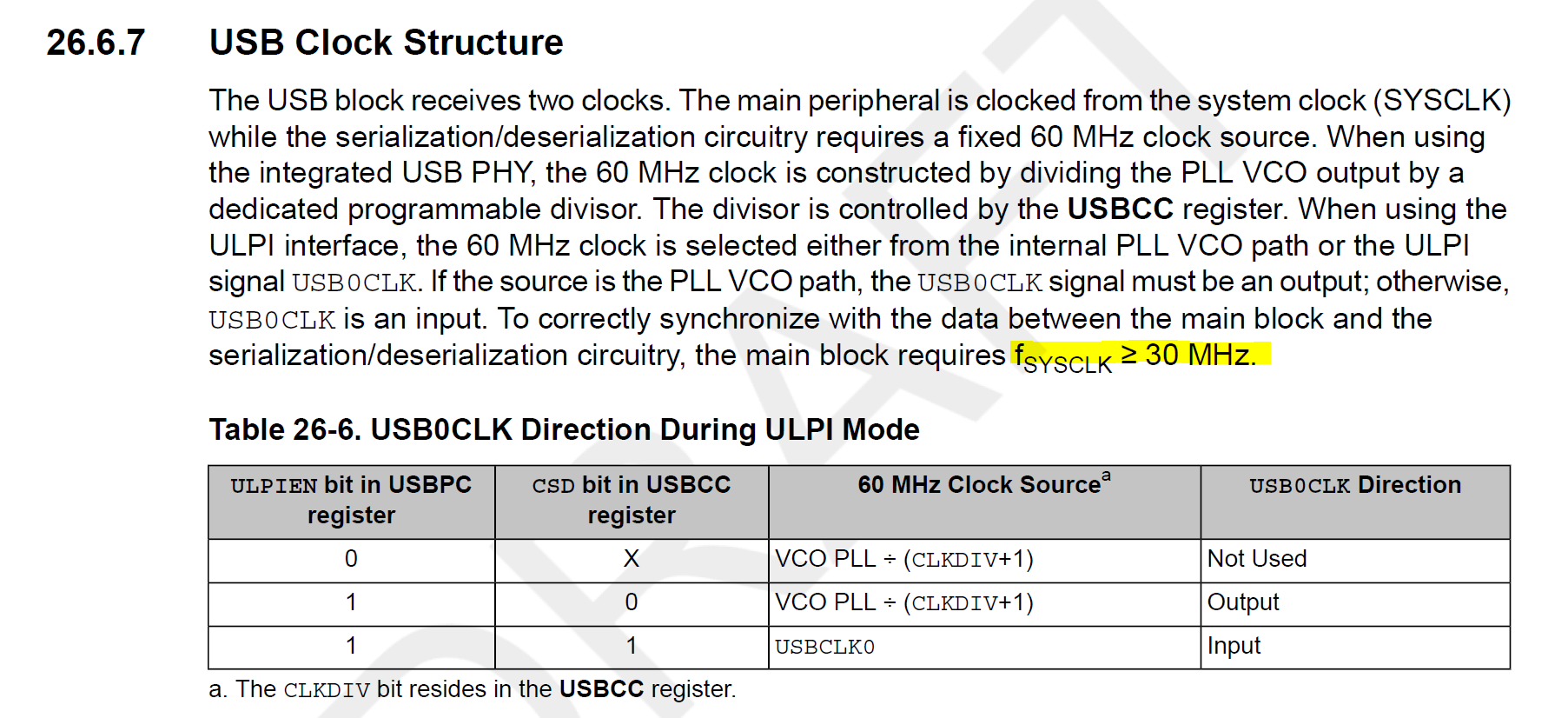
Looking for suggestions on this, or similar experience, or whether or not there a lower limit to sysclk when using USB.  Again the PLL remains at 480, so the USB controller in the TIVA should be fine.

Thank you and regards,


Tim

  • Hello Tim,

    I have not tried to lower the system clock speed with USB but based on what you've described that 30MHz is fine and 12MHz is not and that you are seeing missed inputs, I suspect that the microcontroller is running too slow to process APIs in the USB stack before timeouts occur.

    Some checks you can do to make sure configuration is not an issue:

    Is the SysTick still running at 1 millisecond?

    Did you pass in the new clock value to the USB stack via the USBDCDFeatureSet API using USBLIB_FEATURE_CPUCLK?

    If those are all good, I strongly suspect the USB stack just isn't being given enough CPU cycles before a timeout occurs. We have not experimented for a lowest clock speed for USB, the recommendation has always been to run at 120 MHz for USB, and I don't really have a setup to evaluate the stability of the stack in a full application context to the extent that I would feel comfortable giving you a green limit for a minimum clock speed. I would recommend you evaluate and stress test your system to find out what that lower limit is at whether that be 30MHz or even lower.

    You may also want to try adding the library files to your project to see what APIs you are stuck in and then could attempt to tweak the USB library. To do so you would unlink usblib.lib and manually add the requisite .c files to your project. This gives you visibility into the USB stack for further debugging.

  • Thanks for the rapid response, Ralph.

    Regarding FEATURE_CPUCLK, this is not used in the device portion of usblib;  it does appear to be used in the host portion but not the device portion. 

    We are using the lib files and I have been able to instrument them.  Interrupt rates, latency, and response times look OK but this is still being investigated.

    Since sysclk is slower, the rate at which SYSTICK counts down is slower.  However, it appears that the usb device driver informs the hardware of the PLL frequency only (in device mode), and not the system clock frequency.  The USB controller continues to generate SOF interrupts at a 1KHz rate, with some variance.

    The other software may be introducing too much interrupt latency at this slow clock rate;  I am still looking into this. 

  • Hello Tim,

    I honestly hadn't looked into the specifics of USBDCDFeatureSet before so it looks like you are right, only host uses that.

    I wonder if normalizing SysTick to 1 millisecond would help. I feel that should be possible. The API should be using the clock value to be configured.

        SysTickPeriodSet(g_ui32SysClock / SYSTICKS_PER_SECOND);
    

    Based on that, I would think that it should run at 1 millisecond still. Unless you just mean the actual count for it updates slower? I don't think the count is used by anything in the application so that would be fine if so.

    Have you seen if the variance for the 1KHz interrupt rate occurs at 30 MHz too? If not, maybe that is an indicator.

  • I see no dependencies on systick within the driver.  Also, since all works well for SYSCLK of 30MHz and higher, and since our app and our environment does not use SYSTICK  (we use 3 other TI timers for various timing intervals), I suggest that the USB driver does not have a dependency on SYSTICK. The only references I could find were in dfu, which we do not use, where the software disables and re enables the systick interrupt before updating firmware.

    I note that no matter what value we use for sysclk (120 MHz, 30 MHz, etc), we log SOF interrupts at 1mS intervals as measured by the other TI timers that we use (our code does change the countdown values for these timers when we change SYSCLK). 

    If, however, you can point to a place in the library where SYSTICK is used, we will be happy to initialize it and employ it.  I saw no such place, so it sounds like a "guess,"  but by all means please correct me if I am wrong on this.

    Regards,

    Tim

  • Some other information:  I've updated the TIVAWare USB driver to revision 2.2.0.295; there are no changes in behavior. 

    I also introduced systick and used a fairly high clock rate (5129 ticks per second):  this ensures that the interrupt rate is high and is not a multiple of 1mS.  The ISR simply determines the latency (since systick continues to count down).  The sources of latency are 1) the software has some places where interrupts must be disabled, and 2) there are other interrupts that require servicing (timers, uart). 

    Tests at 120MHz show a mean latency of 2uSec and a max latency of 7uSec.

    Tests at 15MHz (where USB starts to misbehave) show a mean latency of 2 uSec and a max of 194 uSec. 

    At 30MHz, mean latency is 2 usec and max is 33uSec without USB activity, and 135uSec with USB activity.

  • Hello Tim,

    I did some more digging into the USB layers and you are right about SysTick. I never had dug into that before but I was under the wrong impression that SysTick was used by the USB library. For the record, I did not write the USB library myself, but I have been supporting it to the best of my ability for the past three years. Unfortunately it was designed to be unnecessarily complex and it can be hard to trace through it in order to really understand what is going on under the hood.

    194 uSec of latency doesn't feel like it should be enough to disrupt the actual USB communication over the bus.

    Are you testing this on LaunchPad? I have a USB analyzer so maybe I can re-create the test and then look over the USB analyzer to see if I notice anything like dropped packets etc.

  • Hello Ralph,

    No need to apologize;  we are all deep diving into this for the first time and USB drivers are always fairly involved.

    This is on our target system, which has been around for a few years now.  It has a fair number of features, so porting a subset to a launchpad or to an eval board is not an easy option though we should keep it on the table. 

    BTW, our board also has SDRAM off of EPI;  as an experiment I changed our software to ensure the USB buffers were in interal SRAM instead of SDRAM;  this made no difference.

    Thanks,

    Tim

  • Hi Tim,

    So I tried to re-create this with our LaunchPad example and I am not even making as much progress as you are. At 60 MHz it seems to work well, but at 30 MHz, the TM4C LaunchPad already fails Windows USB enumeration. I think Windows is rather demanding with how many commands it sends so that doesn't floor me, but it was not as robust as I expected given what you've seen.

    But given that is already where the USB interface stops working for a LaunchPad + Windows 10 setup, I would say if you are getting 30 MHz to work reliably, then you probably are in good shape and close to the limits already.

  • I  am curious: when it does fail, do you have insight into the failure mode?

    - has processor halted?

    - is processor locked up, perpetually servicing an interrupt?

    - Or, has the state machinery on the TIVA side simply confused about the next step because it dropped something/didn't see something?

    My interest is because a faster clock rate may not eliminate the problem but simply reduce the likelihood of it occurring to the point where it is so infrequent that a failure is not attributed to USB.

    Tim

  • Hello Tim,

    The MCU is running and not locked up, I can pause and it is in the main while(1) loop for the application and breakpoints work fine.

    At 30 MHz, the TM4C is seeing packets come in from the host PC, but it is not responding to them. I see ACK's on the USB bus, but I don't see subsequent data output.

    When the clock speed is set to 15MHz, the USB interface does not appear to be enabled properly. My USB analyzer won't even trigger to view any traffic because the PC doesn't even notice a USB device has been connected.

  • Hello Tim,

    It looks like 30MHz is the minimum system frequency based on the peripheral hardware design:

    That said, since I wasn't able to get it working at 30 MHz on my end... I would strongly recommend you stress test the system at 30 MHz to make sure it will work reliably for you in all situations. I have reasonable concern about the viability of 30 MHz given that it won't even enumerate with Windows.

  • Ralph,

    What document is this?  The TIVA manual I have does not expound on the USB controller register contents.  Also, we are internal phy, FS only (not ULPI), so the description above seems a bit vague insofar as use of the internal phy vs an external ULPI phy.

    Regards,

    Tim

  • Hello Tim,

    The USB Chapter of the datasheet is protected under an NDA agreement. If you go to the USB section, there is a document link to where you can agree to the NDA terms and download the datasheet.

    For your device, that would be this link: http://www.ti.com/lit/pdf/spms416

    That would provide you the full chapter where you can find that information. Search for USB Clock Structure as that image came from a different device datasheet so it probably won't match the section number.