This thread has been locked.

If you have a related question, please click the "Ask a related question" button in the top right corner. The newly created question will be automatically linked to this question.

TM4C1294NCPDT: Debugging MCU on custom board

Part Number: TM4C1294NCPDT
Other Parts Discussed in Thread: EK-TM4C1294XL

Hello,

I designed my own custom board which has TM4C1294NCPDT. I want to use EK-TM4C1294XL as programmer for my custom board. But I couldnt program my custom device's TM4C1294NCPDT.

- I removed R40, R8, R10, R11 R15 and R16 on EK-TM4C1294XL.

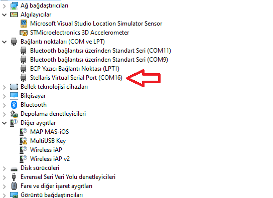
- I have "Stellaris Virtual Serial Port" on my device manager.

- I have 10-pin connector with ribbon cables to make connection between my custom board and EK-TM4C1294XL.

- Here is my schematic:

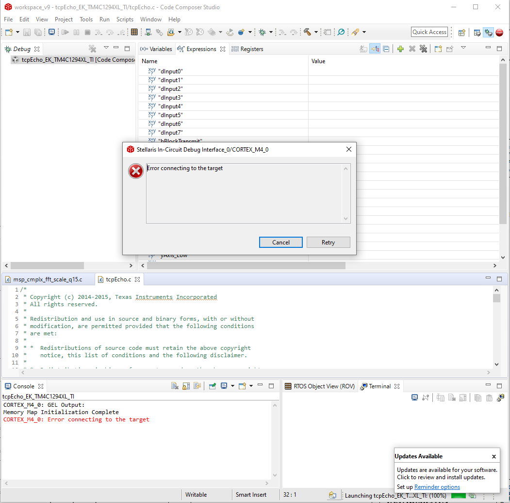
Do you have any idea why I cant program my custom device?

Best regards,

Onur

  • Hi,

      I notice your RBIAS pin is connected to GND. There is an errata that requires RBIAS be connected to GND via a 4.7k resistor. Please see below. 

    Please also go through section 4.8 of this app note about using the EK-TM4C129XL as a ICDI debug probe to debug your target system. 

  • Charles Tsai said:
    I notice your RBIAS pin is connected to GND.

    Looking at the posted schematic, isn't the RBIAS pin connected to ground via R43 which is a 4.87K resistor?

  • Hi Chester,

      Looking at the schematic again, it is indeed connected via the resistor. I thought it was connected to GND directly. Thanks for catching the mistake. 

  • Hello,

    I forgot to post the error:

    I will solder another PCB, totally different from this PCB. I will write here again. 

    Also this MCU was bought in August 2018. I have new MCUs which came last week. I dont know if time effects. I dont know, I worked hard and studied the EK-TM4C1294XL.

    Onur

  • Hi,

      Let me know the result of your second board. Can you also follow the connection shown in the below table. You can find the detail in the app note I sent in my first reply. There is a recommendation of a pullup on the nRESET pin but I don't see it in your schematic. Another thing I will suggest you try is to use your EK-TM4c1294XL board to debug another EK-TM4C1294XL board. This way you can find out if the problem is with your custom board or with the debug output from the EK-TM4C1294XL. In another word, if also fail to debug your second EK-TM4C1294XL board then the problem may lay with your first EK-TM4C1294XL board which acts as the debug probe.

  • Hi Onur,

    I don't see listed (windows device manger) a connected USB to XDS1xx driver being loaded. The virtual COM16 is not the JTAG connection. Charles idea to use a lunch pad JTAG port to flash your custom board requires a few strap changes to isolate it from the local target MCU for remote target use. Anyway if you plug in launch pad debug port to computer USB, debug probe drivers should show up in device manager. 

    Launch pad R8,10,11,15,16, 40 has to be removed and J6 has 10 pin ribbon cable for JTAG your board.

  • Hello guys,

    In my soldering, I found a mistake. I soldered 51K instead of 51R for R46. Please have a look below:

    I removed 51K and soldered 51R. 

    It didnt work after correcting R46. But it is a very complex PCB. Maybe it has another mistakes.

    I soldered a different but simpler PCB which has TM4C1294NCPDT. It worked easily. JTAG U6 connector has no problem. Thank you!