


I was working on the UART1 of the TM4c123GXL before doing this i tried to echo characters on the UART0 using "TivaWare_C_Series-2.2.0.295\examples\boards\ek-tm4c123gxl\uart_echo" which was successful. Then i tried the same code for UART1 by making small changes but still characters are not getting printed.
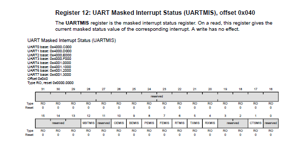
Also while debugging i put breakpoint over this line "ui32Status = MAP_UARTIntStatus(UART1_BASE, true);" i observed i'm getting 0x40 value in the "ui32Status" that means in the "MIS" register "RTMIS" bit is getting set whenever we put data on the UART1. What does that exactly mean?? i read data sheet but i didn't got any idea.
When i send character "G" via serial terminal i saw data register of the UART1 changed.

One more thing i observed whenever we enter any character control is going into the uart handler. Then what should be the reason for not printing on the terminal??
I'm attaching code as well as register pics. Any help will be really
appreciated. Thank you.
#include <stdint.h>
#include <stdbool.h>
#include "inc/hw_ints.h"
#include "inc/hw_memmap.h"
#include "driverlib/debug.h"
#include "driverlib/fpu.h"
#include "driverlib/gpio.h"
#include "driverlib/interrupt.h"
#include "driverlib/pin_map.h"
#include "driverlib/rom.h"
#include "driverlib/rom_map.h"
#include "driverlib/sysctl.h"
#include "driverlib/uart.h"


//*****************************************************************************
//
// The UART interrupt handler.
//
//*****************************************************************************
void
UARTIntHandler(void)
{
    uint32_t ui32Status;

    //
    // Get the interrrupt status.
    //
    ui32Status = MAP_UARTIntStatus(UART1_BASE, true);

    //
    // Clear the asserted interrupts.
    //
    MAP_UARTIntClear(UART1_BASE, ui32Status);

    //
    // Loop while there are characters in the receive FIFO.
    //
    while(MAP_UARTCharsAvail(UART1_BASE))
    {
        //
        // Read the next character from the UART and write it back to the UART.
        //
        MAP_UARTCharPutNonBlocking(UART1_BASE, MAP_UARTCharGetNonBlocking(UART1_BASE));

        //
        // Blink the LED to show a character transfer is occuring.
        //
        GPIOPinWrite(GPIO_PORTF_BASE, GPIO_PIN_2, GPIO_PIN_2);

        //
        // Delay for 1 millisecond.  Each SysCtlDelay is about 3 clocks.
        //
        SysCtlDelay(SysCtlClockGet() / (1000 * 3));

        //
        // Turn off the LED
        //
        GPIOPinWrite(GPIO_PORTF_BASE, GPIO_PIN_2, 0);

    }
}

//*****************************************************************************
//
// Send a string to the UART.
//
//*****************************************************************************
void
UARTSend(const uint8_t *pui8Buffer, uint32_t ui32Count)
{
    //
    // Loop while there are more characters to send.
    //
    while(ui32Count--)
    {
        //
        // Write the next character to the UART.
        //
        MAP_UARTCharPutNonBlocking(UART1_BASE, *pui8Buffer++);
    }
}

//*****************************************************************************
//
// This example demonstrates how to send a string of data to the UART.
//
//*****************************************************************************
int
main(void)
{
    //
    // Enable lazy stacking for interrupt handlers.  This allows floating-point
    // instructions to be used within interrupt handlers, but at the expense of
    // extra stack usage.
    //
    MAP_FPUEnable();
    MAP_FPULazyStackingEnable();

    //
    // Set the clocking to run directly from the crystal.
    //
    MAP_SysCtlClockSet(SYSCTL_SYSDIV_1 | SYSCTL_USE_OSC | SYSCTL_OSC_MAIN |
                       SYSCTL_XTAL_16MHZ);

    //
    // Enable the GPIO port that is used for the on-board LED.
    //
    MAP_SysCtlPeripheralEnable(SYSCTL_PERIPH_GPIOF);

    //
    // Enable the GPIO pins for the LED (PF2).
    //
    MAP_GPIOPinTypeGPIOOutput(GPIO_PORTF_BASE, GPIO_PIN_2);

    //
    // Enable the peripherals used by this example.
    //
    MAP_SysCtlPeripheralEnable(SYSCTL_PERIPH_UART1);
    MAP_SysCtlPeripheralEnable(SYSCTL_PERIPH_GPIOC);

    //
    // Enable processor interrupts.
    //
    MAP_IntMasterEnable();

    //
    // Set GPIO A0 and A1 as UART pins.
    //
    GPIOPinConfigure(GPIO_PC5_U1TX);
    GPIOPinConfigure(GPIO_PC4_U1RX);
    MAP_GPIOPinTypeUART(GPIO_PORTC_BASE, GPIO_PIN_5 | GPIO_PIN_4);

    //
    // Configure the UART for 115,200, 8-N-1 operation.
    //
    MAP_UARTConfigSetExpClk(UART1_BASE, MAP_SysCtlClockGet(), 115200,
                            (UART_CONFIG_WLEN_8 | UART_CONFIG_STOP_ONE |
                             UART_CONFIG_PAR_NONE));

    //
    // Enable the UART interrupt.
    //
    MAP_IntEnable(INT_UART1);
    MAP_UARTIntEnable(UART1_BASE, UART_INT_RX | UART_INT_RT);

    //
    // Prompt for text to be entered.
    //
    UARTSend((uint8_t *)"\033[2JEnter text: ", 16);

    //
    // Loop forever echoing data through the UART.
    //
    while(1)
    {
    }
}


