This thread has been locked.

If you have a related question, please click the "Ask a related question" button in the top right corner. The newly created question will be automatically linked to this question.

TM4C1294NCPDT: Is C-R-C network a reliable solution?

Part Number: TM4C1294NCPDT

Hi,

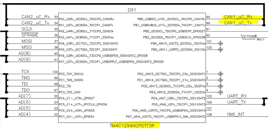
I am writing to you because of a question about the use of the TM4C1294NCPDTT3R or the point GPIO#09 in the Errata document (www.ti.com/.../spmz850g.pdf).
Unfortunately we are dependent on the two pins PB0 and PB1.

The first thought was to provide the output with a C-R-C network so that the edge steepness is always >> 2ns.
But we don't really trust this solution, because instead of this simple solution the Errata document recommends "Do not use PB0 and PB1" as workaround.

Can you please find out if a C-R-C network is a reliable solution?
Are there already implementations and experiences with other designs?

Thanks

Fred

  • Using slope control on PB0 and PB1 is an effective means of avoiding this problem. If you are routing these pins to a CAN transceiver and the traces are short, that will help in the prevention of coupled noise causing fast transients. Look at the rise/fall times of your existing solutions. Adding a series resistor may be sufficient. If capacitance is needed, add it between the resistor and the CAN transceiver for PB1 (CAN1TX), but on PB0 (CAN1RX) add it between the resistor and pin PB0. The 2nS rise/fall time is sufficient. There is no need to add additional margin.