This thread has been locked.

If you have a related question, please click the "Ask a related question" button in the top right corner. The newly created question will be automatically linked to this question.

TM4C123GH6PM: Why the values of the MIS and RIS registers are changing for the interrupt at the same gpio pin??

Part Number: TM4C123GH6PM
Other Parts Discussed in Thread: EK-TM4C123GXL

I'm trying to interface the 7 swiches which will work as a menu, up, down ect. They are connected to the controller as follows


Help -  (PF0)
Left -  (PA5)
Down -  (PA2)
Right - (PA3)
Enter - (PA4)
Up -    (PA6)
Menu -  (PA7)
Esc -   (PF1)

When i pressed the menu switch i tried to observe the Raw interrupt status as well as Masked interrupt status register values. Here one thing i observed is  if  i pressed the Menu button for the several times i was getting different values Here i'm attaching screenshots below,

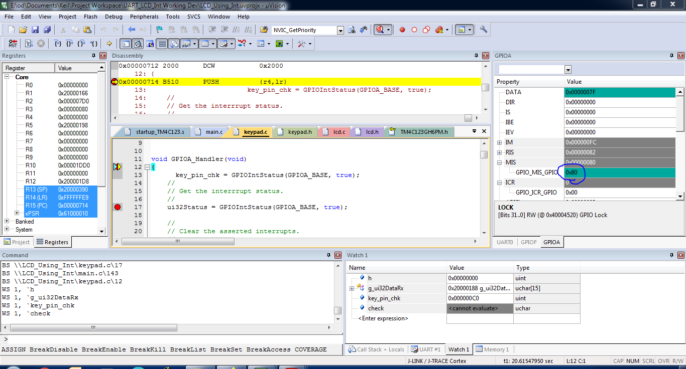
If we compare both the pics we can see the different values coming for the same interrupt. What should be the reason for this??

Also my next tasks are dependent upon which pin is pressed so any other suggestions to get know which pin is pressed at a particular time will be also helpful for me.
Any help will be really appreciated.

void GPIOA_Handler(void)
{
			key_pin_chk = GPIOIntStatus(GPIOA_BASE, true);
    //
    // Get the interrrupt status.
    //
    ui32Status = GPIOIntStatus(GPIOA_BASE, true);

    //
    // Clear the asserted interrupts.
    //
    GPIOIntClear(GPIOA_BASE, ui32Status);
	
		g_bIntFlagA = true; 
	
}
	

void GPIOF_Handler(void)
{
    uint32_t ui32Status;
			key_pin_chk = GPIOIntStatus(GPIOF_BASE, true);
    //
    // Get the interrrupt status.
    //
    ui32Status = MAP_GPIOIntStatus(GPIO_PORTF_BASE, true);

    //
    // Clear the asserted interrupts.
    //
    MAP_GPIOIntClear(GPIO_PORTF_BASE, ui32Status);
	
	  key_pin_chk = GPIOPinRead(GPIO_PORTF_BASE,GPIO_PIN_1 | GPIO_PIN_0);

		g_bIntFlagF = true;
}

  • HI,

      You mask the lower two bits using the IM register. This means you only allow GIOA[7:2] to generate interrupts. If you look at the first picture the RIS is 0x82. RIS=0x82 AND IM=0xFC gives you MIS=0x80. In the second picture the RIS is 0xC2. RIS=0xC2 AND IM=0xFC gives you MIS=0xC0. I don't understand what is not clear to you. It is behaving the way it should. In the second picture, edges are detected on GIOA7 and GIOA6 while the first picture shows only GIOA7 is detected for interrupt. Note that your mask the lower two bits (GiOA1 and GIOA0) for interrupt generation. In the second picture you might have pressed two pins at the same time. Do you have debouncer circuit in your design? If you don't have a debouncer circuit it is also possible that the input signal can bounce several times before setting to its final state. In this case, instead of seeing one interrupt you may see multiple interrupts coming from the same pin. You need to watch out for that and add debouncer either in software or in hardware.

      In your GIOA ISR you just need to decode your key_pin_chk variable to find out which pin generate interrupt and take the action accordingly.


  • Hello, "If you look at the first picture the RIS is 0x82. RIS=0x82 AND IM=0xFC gives you MIS=0x80. In the second picture the RIS is 0xC2. RIS=0xC2 AND IM=0xFC gives you MIS=0xC0." this line cleared my confusion. Thank you so much.

    As you said may be I have pressed 2 switches a time but that is not the case, also I haven't added de bouncer circuit. How can I add debouncer in software??

    Regards,

    Omkar

  • Hi,

      Here is one article that talks about  software debouncer. https://reference.digilentinc.com/learn/microprocessor/tutorials/debouncing-via-software/start#:~:text=Software%20debouncing%20is%20accomplished%20by,whether%20consecutive%20samples%20are%20received.

      TivaWare also implements debouncer in C:\ti\TivaWare_C_Series-2.2.0.295\examples\boards\ek-tm4c123gxl\drivers\buttons.c file. Look at how it is done in ButtonsPoll() function.

  • Hello

    I tried the following way which actually worked for me

    		key_pin_chk = GPIOIntStatus(GPIOF_BASE, true);

    by using "key_pin_chk" variable in the handler, I'm checking the status of the MIS register so according the recived values after pressing every switch i have made the following function which is doing further work. So i skipped software denouncing at least for now.

    //*****************************************************************************
    //! Whenever the keypad interrupt occures this function will get called 
    //! \param key_pin_chk in the interrupt handler, we are checking the value of
    //!	   the register MIS(Masked Interrupt Status) by using this value
    //!	   we will get to know exact which interrupt occured a that time.
    //!	   So, according to the value of that variable functions will be 
    //!	   called.
    //!
    //*****************************************************************************
    
    void keypad_interrupt(uint32_t key_pin_chk)
    {
    	if(key_pin_chk == 0xC0 || key_pin_chk == 0x80)
    		{
    			menu_pressed();
    		}
    		else if(key_pin_chk == 0x08 || key_pin_chk == 0x0C)
    				{
    					right_pressed();
    				}
    			else if(key_pin_chk == 0x18 || key_pin_chk == 0x10)
    					{
    						enter_pressed();
    					}
    				else if(key_pin_chk == 0x02 || key_pin_chk == 0x03)
    						{
    							esc_pressed();
    						}	
    }