This thread has been locked.

If you have a related question, please click the "Ask a related question" button in the top right corner. The newly created question will be automatically linked to this question.

CCS/TM4C129XNCZAD: how to set timer value of 20 ms in timer

Part Number: TM4C129XNCZAD


Tool/software: Code Composer Studio

Hi,

I am using customized tm4c129xnczad controller. I need to set timer of 20ms .can you please suggest me how to set timer  for system clock 25 mhz and please let me know the calculation to set the timer value in 

 TimerLoadSet(TIMER0_BASE, TIMER_B, ui32SysClock / 1000);

I am attaching the program here

ui32SysClock = SysCtlClockFreqSet((SYSCTL_XTAL_25MHZ |
SYSCTL_OSC_MAIN |
SYSCTL_USE_OSC), 25000000);

TimerLoadSet(TIMER0_BASE, TIMER_B, ui32SysClock / 1000);

  • Hello Chandana,

    So what you've posted here:

    TimerLoadSet(TIMER0_BASE, TIMER_B, ui32SysClock / 1000);

    Is setting the timer to run at 1 millisecond.

    The way this works is the timer runs off the system clock so every cycle of the clock, the timer count increments. By loading in a value of System Clock / 1000, you are telling it that you want the timer to trigger at a period of (System Clock / 1000). The actual period (converting the system clock to seconds) then will be [(System Clock / 1000) * (1 / System Clock)] = 1/1000 seconds, i.e. 1 millisecond.

    To get to 20 milliseconds, you want the timer to trigger more often, which means you want the count inside of the timer to be proportionally smaller.

    Therefore you would want to divide the system clock by a larger value. So for 20 milliseconds you would want the following:

    TimerLoadSet(TIMER0_BASE, TIMER_B, ui32SysClock / 20000);

  • Hi,

    Thanks for the reply.

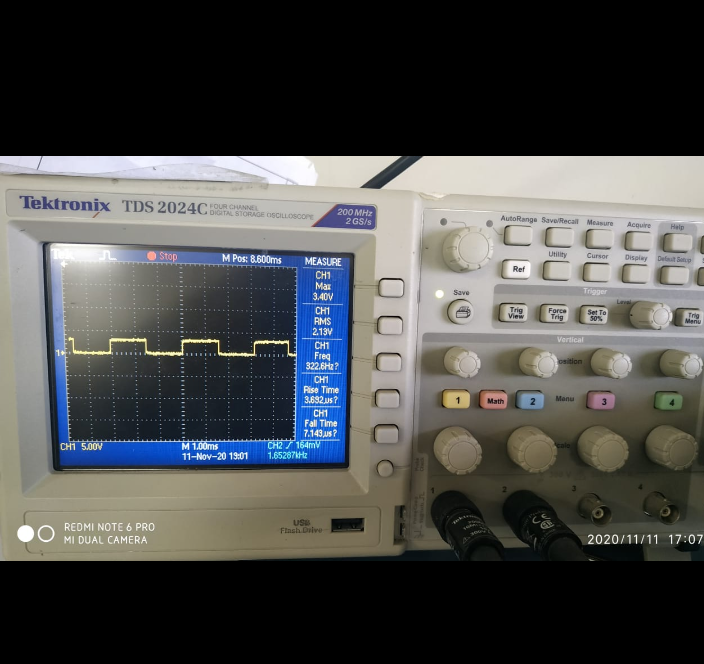
    I have tried set the timer value of 1ms by setting like this TimerLoadSet(TIMER0_BASE, TIMER_B, ui32SysClock / 1000); and we tried to make the led pin high when an interrupt handler occurs and we have incremented the counter value in the interrupt handler so when the counter value is even number we are making led pin high and when the counter value is odd number the led pin is low so, by making like this will get pulse for each cycle. So when we have checked in the oscilloscope we are getting as 7.5 ms as one cycle instead of 1ms.So  i am here by attaching the code so please tell me what is the problem and how to achieve 1ms and 20 ms.
    #include <stdlib.h>
    #include <stdio.h>
    #include <stdbool.h>
    #include <stdint.h>
    #include "inc/hw_ints.h"
    #include "inc/hw_memmap.h"
    #include "driverlib/gpio.h"
    #include "driverlib/interrupt.h"
    #include "driverlib/pin_map.h"
    #include "driverlib/sysctl.h"
    #include "driverlib/timer.h"
    #include "driverlib/uart.h"
    #include "utils/uartstdio.h"
    #include "inc/hw_types.h"
    #include "driverlib/rom.h"
    #include "driverlib/rom_map.h"
    #include "grlib/grlib.h"
    #include "drivers/frame.h"
    #include "drivers/kentec320x240x16_ssd2119.h"
    #include "drivers/pinout.h"
    #include "driverlib/debug.h"
    
    //! This example uses the following interrupt handlers.  To use this example
    //! in your own application you must add these interrupt handlers to your
    //! vector table.
    //! - INT_TIMER0B - Timer0BIntHandler
    //
    //*****************************************************************************
    
    //*****************************************************************************
    //
    // Number of interrupts before the timer gets turned off.
    //
    //*****************************************************************************
    #define NUMBER_OF_INTS          1000
    
    //*****************************************************************************
    //
    // Counter to count the number of interrupts that have been called.
    //
    //*****************************************************************************
    static volatile uint32_t g_ui32Counter = 0;
    
    
    //*****************************************************************************
    //
    // The interrupt handler for the Timer0B interrupt.
    //
    //*****************************************************************************
    void
    Timer0BIntHandler(void)
    {
        //
        // Clear the timer interrupt flag.
        //
        TimerIntClear(TIMER0_BASE, TIMER_TIMB_TIMEOUT);
    
        //
        // Update the periodic interrupt counter.
        //
        g_ui32Counter++;
        if(g_ui32Counter % 2 == 0)
        {
            GPIOPinWrite(GPIO_PORTF_BASE, GPIO_PIN_7, GPIO_PIN_7);
        }
        else
        {
            GPIOPinWrite(GPIO_PORTF_BASE, GPIO_PIN_7, 0x00);
        }


        //
        // Once NUMBER_OF_INTS interrupts have been received, turn off the
        // TIMER0B interrupt.
        //
      /*  if(g_ui32Counter == NUMBER_OF_INTS)
        {
            //
            // Disable the Timer0B interrupt.
            //
            IntDisable(INT_TIMER0B);
    
            //
            // Turn off Timer0B interrupt.
            //
            TimerIntDisable(TIMER0_BASE, TIMER_TIMB_TIMEOUT);
    
            //
            // Clear any pending interrupt flag.
            //
            TimerIntClear(TIMER0_BASE, TIMER_TIMB_TIMEOUT);
        }
    */
    }
    
    //*****************************************************************************
    //
    // Configure Timer0B as a 16-bit periodic counter with an interrupt
    // every 1ms.
    //
    //*****************************************************************************
    int
    main(void)
    {
    #if defined(TARGET_IS_TM4C129_RA0) ||                                         \
        defined(TARGET_IS_TM4C129_RA1) ||                                         \
        defined(TARGET_IS_TM4C129_RA2)
        uint32_t ui32SysClock;
    #endif
    
        uint32_t ui32PrevCount = 0;
    
        //
        // Set the clocking to run directly from the external crystal/oscillator.
        // TODO: The SYSCTL_XTAL_ value must be changed to match the value of the
        // crystal on your board.
        //
    #if defined(TARGET_IS_TM4C129_RA0) ||                                         \
        defined(TARGET_IS_TM4C129_RA1) ||                                         \
        defined(TARGET_IS_TM4C129_RA2)
        ui32SysClock = SysCtlClockFreqSet((SYSCTL_XTAL_25MHZ |
                                           SYSCTL_OSC_MAIN |
                                           SYSCTL_USE_OSC), 25000000);
    #else
        SysCtlClockSet(SYSCTL_SYSDIV_1 | SYSCTL_USE_OSC | SYSCTL_OSC_MAIN |
                       SYSCTL_XTAL_16MHZ);
    #endif
    
        //
        // The Timer0 peripheral must be enabled for use.
        //
        SysCtlPeripheralEnable(SYSCTL_PERIPH_TIMER0);
    
        //
        // Set up the serial console to use for displaying messages.  This is
        // just for this example program and is not needed for Timer operation.
        //
        InitConsole();
    
        //
        // Display the example setup on the console.
        //
        UARTprintf("16-Bit Timer Interrupt ->");
        UARTprintf("\n   Timer = Timer0B");
        UARTprintf("\n   Mode = Periodic");
        UARTprintf("\n   Number of interrupts = %d", NUMBER_OF_INTS);
        UARTprintf("\n   Rate = 20ms\n\n");
    
        //
        // Configure Timer0B as a 16-bit periodic timer.
        //
        TimerConfigure(TIMER0_BASE, TIMER_CFG_SPLIT_PAIR | TIMER_CFG_B_PERIODIC);
    
        //
        // Set the Timer0B load value to 1ms.
        //
    #if defined(TARGET_IS_TM4C129_RA0) ||                                         \
        defined(TARGET_IS_TM4C129_RA1) ||                                         \
        defined(TARGET_IS_TM4C129_RA2)
        TimerLoadSet(TIMER0_BASE, TIMER_B,ui32SysClock /10);         //change by mukesh 1000
    #else
        TimerLoadSet(TIMER0_BASE, TIMER_B, SysCtlClockGet() /1000);
    #endif
    
        //
        // Enable processor interrupts.
        //
        IntMasterEnable();
    
        //
        // Configure the Timer0B interrupt for timer timeout.
        //
        TimerIntEnable(TIMER0_BASE, TIMER_TIMB_TIMEOUT);
    
        //
        // Enable the Timer0B interrupt on the processor (NVIC).
        //
        IntEnable(INT_TIMER0B);
    
        //
        // Initialize the interrupt counter.
        //
        g_ui32Counter = 0;
    
        //
        // Enable Timer0B.
        //
        TimerEnable(TIMER0_BASE, TIMER_B);
    
        //
        // Loop forever while the Timer0B runs.
        //
    
        volatile uint32_t ui32Loop;
    
    
           // Enable the GPIO port that is used for the on-board LED.
           //
           SysCtlPeripheralEnable(SYSCTL_PERIPH_GPIOF);
    
           //
           // Check if the peripheral access is enabled.
           //
           while(!SysCtlPeripheralReady(SYSCTL_PERIPH_GPIOF))
           {
           }
    
           //
           // Enable the GPIO pin for the LED (PQ7).  Set the direction as output, and
           // enable the GPIO pin for digital function.
           //
           GPIOPinTypeGPIOOutput(GPIO_PORTF_BASE, GPIO_PIN_7);
    
        while(1)
        {
            //
            // If the interrupt count changed, print the new value
            //
            //if(ui32PrevCount != g_ui32Counter)
            //{
                //
                // Print the periodic interrupt counter.
                //
                UARTprintf("Number of interrupts: %d\r", g_ui32Counter);
                ui32PrevCount = g_ui32Counter;
                //UARTprintf("g_ui32Counter");


        }
    }


  • Hello Chandana,

    I haven't figured out the reasoning why but it looks like the timer is running off of a different clock when you configure the system clock that way. It seems to be running at 16MHz which makes me think it is running from the PIOSC.

    The easiest way to solve this is to use the PLL instead which also gives you a better performing system clock. Try using this and see if you can get the timer working accurately:

        ui32SysClock = SysCtlClockFreqSet((SYSCTL_XTAL_25MHZ |
                                               SYSCTL_OSC_MAIN |
                                               SYSCTL_USE_PLL |
                                               SYSCTL_CFG_VCO_480), 120000000);

  • Hi,

    Thanks for the reply and sorry for the late reply.

    I have tried by making changes  by like this .

    ui32SysClock = SysCtlClockFreqSet((SYSCTL_XTAL_25MHZ |
                                       SYSCTL_OSC_MAIN |
                                       SYSCTL_USE_PLL |
                                       SYSCTL_CFG_VCO_480), 120000000);
    
    TimerLoadSet(TIMER0_BASE, TIMER_B,ui32SysClock /1000);

    but still i am getting as 2ms for this load set. But it should get as 1ms .
    please tell me how to resolve this. please Tell me what value we have to set for 20ms in timer load set.. please help me with this.
    I am attaching the CRO output .Please tell me how to resolve this.

  • Hello Chandana,

    The o-scope doesn't seem to be well configured to me since I see the frequency comes with a ? next to it which indicates uncertainty in the measurement. 

    I verified the changes again on my end and it creates a uniform 1ms / 1 kHz waveform seen by my logic state analyzer.

    For 20 ms you would use

    TimerLoadSet(TIMER0_BASE, TIMER_B,ui32SysClock /20000);

    as I reported in a prior post.