This thread has been locked.

If you have a related question, please click the "Ask a related question" button in the top right corner. The newly created question will be automatically linked to this question.

MSP432P401R: Cannot Start Up I2C

Part Number: MSP432P401R
Other Parts Discussed in Thread: TLV320AIC3254

Hi,

I am working with C:\ti\Connectivity\CC256X BT\CC256x MSP432 Bluetopia SDK\v4.2.1.1\Samples\A3DPDemo_SRC  sample project which has I2C communication with TI TLV320AIC3254 CODEC for the Audio Boost example.  I am trying to reuse the initialization of the I2C of this project in our own development board along with its communication interface.

I2C Slave Address:  0x22

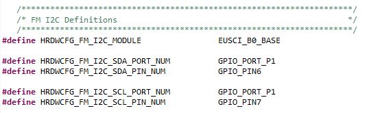
Port Pins:  P1.6 & P1.7

#define HRDWCFG_FM_I2C_MODULE                EUSCI_B0_BASE

The original code does not use Interrupts:

So I have not set anything up.  Its all polled.

We have checked out the I2C SDA and CLK lines on the scope and they are high which is expected.

Upon trying to send the first bytes over to our FM Modulator we do not see any movement when the Start Condition is sent.

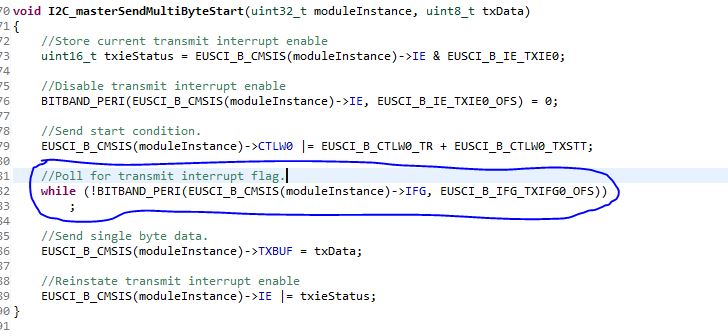
Instead the code hangs while waiting for the transmit Interrupt Flag to be set:

It is obvious that the code has not set up the I2C peripheral correctly.  What am I missing?

Is the I2C peripheral pins from p1.6 & P1.7 tied to EUSCI_B0_BASE or another register  base EUSCI_Bx_BASE???  The technical reference manual does not specify this clearly.

Also, The rest of the code works fine.  All 3 UARTs, BT Stack etc. etc.

Thanks in advance,

Ozzy

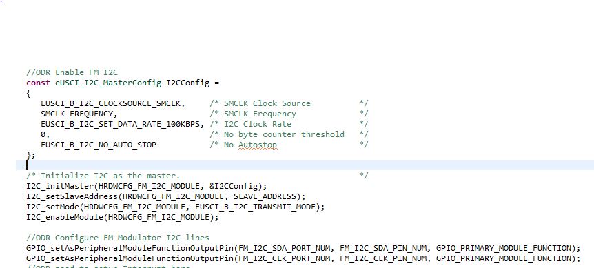
  • Here are my code snippets:

    The code hangs when it tries to send out the Start condition because the interrupt flag is never asserted.

    It seems like the I2C is not even configured correctly .

    Thanks in Advance,

    Ozzy

  • Hi Ozzy,

    I will download the SDK on my side and go through the code and look at it.

    Srinivas

  • Srinivas,

    Do you have any update on this issue?

    Thanks,

    Ozzy

  • Hi Ozzy,

    Ozzy Romero said:
    Is the I2C peripheral pins from p1.6 & P1.7 tied to EUSCI_B0_BASE or another register  base EUSCI_Bx_BASE???  The technical reference manual does not specify this clearly.

    Looking at the device datasheet (www.ti.com/.../msp432p401r), Table 6-62. Port P1 (P1.0 to P1.7) Pin Functions shows P1.6 & P1.7 are tied to UCB0SDA/UCB0SCL which is (EUSCI_B0) while Table 6-76. Port P6 (P6.2 to P6.5) Pin Functions has P6.4 & P6.5 tied to UCB1SDA/UCB1SCL which is (EUSCI_B1).

    The original SDK looks to have used EUSCI_B1 on pins 6.4 & P6.5 and not EUSCI_B0 based on the definitions in HRDWCFG.h.

    #define HRDWCFG_I2C_MODULE EUSCI_B1_BASE

    #define HRDWCFG_I2C_SDA_PORT_NUM GPIO_PORT_P6
    #define HRDWCFG_I2C_SDA_PIN_NUM GPIO_PIN4

    Let me see if there are some differences between EUSCI_B0 & EUSCI_B1 or Ports P1 & P6 that might require some additional configuration.

    Srinivas

  • Hi Ozzy,

    I cannot see any differences in the configuration needs for EUSCI_B0 & EUSCI_B1 in the User's guide. 

    Is it possible to check if it works correctly if you use EUSCI_B1 (P6.4 & P6.5) as in the original SDK example.

    Srinivas

  • Srinivas,

    Our part does not have the I2C on those pins.  

    We are using :  MSP432P401R .

    How ever, we can only use P1.6 & P1.7 for our I2C implementation on our development board.

    Ozzy

  • Hi Ozzy,

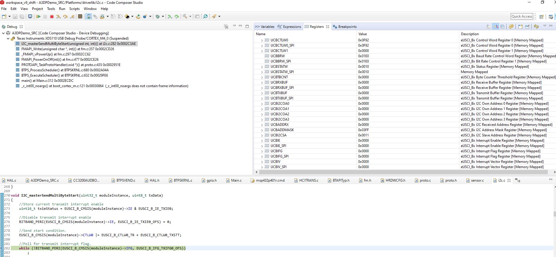
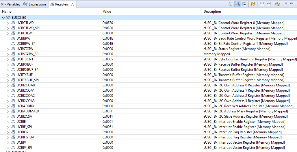
    Can you share the contents of the EUSCI_B0 registers when the SW is stuck in that while loop? It might give some indication of what the problem might be.

    Srinivas

  • Hi Ozzy,

    This is configured for SMCLK as the clock source into the module. It is behaving as if it is not getting any clock into the I2C module. What is the SMCLK source in the system?

    Srinivas

  • Srinivas,

    Yes, I forgot to mention we are using the LFTX clock and DCO which is different than what the default code was using which was the HFTX.

       CS_startLFXT( CS_LFXT_DRIVE1);
       CS_enableDCOExternalResistor();
       CS_setDCOFrequency(48000000);
       CS_initClockSignal(CS_MCLK, CS_DCOCLK_SELECT, MCLK_DIVIDER);
       CS_initClockSignal(CS_SMCLK, CS_DCOCLK_SELECT, HSMCLK_DIVIDER);
       CS_initClockSignal(CS_HSMCLK, CS_DCOCLK_SELECT, SMCLK_DIVIDER);
       CS_initClockSignal(CS_BCLK, CS_LFXTCLK_SELECT,1);
       CS_initClockSignal(CS_ACLK, CS_LFXTCLK_SELECT,1);

    How do I correct the clocking issue?

    Ozzy

  • Yes,

    We are using the the LFTX clock and DCO in our design.

           CS_startLFXT( CS_LFXT_DRIVE1);
           CS_enableDCOExternalResistor();
           CS_setDCOFrequency(48000000);
           CS_initClockSignal(CS_MCLK, CS_DCOCLK_SELECT, MCLK_DIVIDER);
           CS_initClockSignal(CS_SMCLK, CS_DCOCLK_SELECT, HSMCLK_DIVIDER);
           CS_initClockSignal(CS_HSMCLK, CS_DCOCLK_SELECT, SMCLK_DIVIDER);
           CS_initClockSignal(CS_BCLK, CS_LFXTCLK_SELECT,1);
           CS_initClockSignal(CS_ACLK, CS_LFXTCLK_SELECT,1);

    Ozzy

  • Srinivas,

    What is the correct Clock and Frequency selection for the I2C peripheral when you are using LFTX and the DCO?

    Thanks in advance,

    Ozzy

  • Hi Ozzy,

    You say "you are using LFTX and the DCO?" You will use one or the other for I2C. Which one do you want to use?

    As discussed in section 6.1 Clock System Introduction of the TRM (https://www.ti.com/lit/pdf/slau356), you need to specify the source as HSMCLK and cannot directly specify it to be DCOCLK.

    -------------------------------------

    SMCLK: Low-speed subsystem master clock. SMCLK uses the HSMCLK clock resource selection for its clock resource. SMCLK can be divided independently from HSMCLK by 1, 2, 4, 8, 16, 32, 64, or 128. SMCLK is limited in frequency to half of the rated maximum frequency of HSMCLK. SMCLK is software selectable by individual peripheral modules.

    -------------------------------------

    Srinivas

  • Srinivas,

    I have the following clock configuration:

       /* The following constant specifies the low-frequency external       */
       /* oscillator's clock frequency.                                     */
    #define LFXTCLK_FREQUENCY           32768
    #define DCOCLK_FREQUENCY            96000000

       /* The following constants specify information about MCLK.           */
    #define MCLK_SOURCE                 CS_HFXTCLK_SELECT
    #define MCLK_DIVIDER                1
    #define MCLK_FREQUENCY              (DCOCLK_FREQUENCY / MCLK_DIVIDER)

       /* The following constants specify information about HSMCLK.         */
    #define HSMCLK_SOURCE               CS_HFXTCLK_SELECT
    #define HSMCLK_DIVIDER              2
    #define HSMCLK_FREQUENCY            (DCOCLK_FREQUENCY / HSMCLK_DIVIDER)

       /* The following constants specify information about SMCLK. Note     */
       /* that: 1) SMCLK can only be sourced by HSMCLK, 2) the MSPWare APIs */
       /* require you specify HSMCLK's clock source when configuring SMCLK, */
       /* and 3) the divider is relevant to HSMCLK's source.  Also note that*/
       /* in order to support a 2 Mbps UART baud rate SMCLK must run at 24  */
       /* MHz or faster.                                                    */
    #define SMCLK_SOURCE                HSMCLK_SOURCE
    #define SMCLK_DIVIDER               2
    #define SMCLK_FREQUENCY             ((HSMCLK_FREQUENCY * HSMCLK_DIVIDER) / SMCLK_DIVIDER

    And....

           CS_startLFXT( CS_LFXT_DRIVE1);
           CS_enableDCOExternalResistor();
           CS_setDCOFrequency(48000000);
           CS_initClockSignal(CS_MCLK, CS_DCOCLK_SELECT, MCLK_DIVIDER);
           CS_initClockSignal(CS_SMCLK, CS_DCOCLK_SELECT, HSMCLK_DIVIDER);
           CS_initClockSignal(CS_HSMCLK, CS_DCOCLK_SELECT, SMCLK_DIVIDER);
           CS_initClockSignal(CS_BCLK, CS_LFXTCLK_SELECT,1);
           CS_initClockSignal(CS_ACLK, CS_LFXTCLK_SELECT,1);

       const eUSCI_I2C_MasterConfig I2CConfig =
       {
          EUSCI_B_I2C_CLOCKSOURCE_SMCLK,     /* SMCLK Clock Source          */
          SMCLK_FREQUENCY,                   /* SMCLK Frequency             */
          EUSCI_B_I2C_SET_DATA_RATE_100KBPS, /* I2C Clock Rate              */
          0,                                 /* No byte counter threshold   */
          EUSCI_B_I2C_NO_AUTO_STOP           /* No Autostop                 */
       };

    I also tried to use :EUSCI_B_I2C_CLOCKSOURCE_ACLK  for I2C Clock source but that didnt work.

    Are you saying that I have to change of these initializations to get I2C to work :

           CS_initClockSignal(CS_SMCLK, CS_DCOCLK_SELECT, HSMCLK_DIVIDER);
           CS_initClockSignal(CS_HSMCLK, CS_DCOCLK_SELECT, SMCLK_DIVIDER);

    Ozzy

  • Hi Ozzy,

    I think the problem is this:

    #define DCOCLK_FREQUENCY            96000000

    Why is that set to 96 MHz? Later in the code, you have 

    CS_setDCOFrequency(48000000);

    I think you need to use

    #define DCOCLK_FREQUENCY            48000000

    Best practice, would be to use

    CS_setDCOFrequency(DCOCLK_FREQUENCY);

    Hope that resolves the issue.

    Srinivas

  • Srinivas,

    I checked the code and nothing is using DCOCLK_FREQUENCY            96000000  define other than

    #define HSMCLK_FREQUENCY            (DCOCLK_FREQUENCY / HSMCLK_DIVIDER)

    #define MCLK_FREQUENCY              (DCOCLK_FREQUENCY / MCLK_DIVIDER)

    And this is only used to determine other clk: #define SMCLK_FREQUENCY             ((HSMCLK_FREQUENCY * HSMCLK_DIVIDER) / SMCLK_DIVIDER) which is used for

       const eUSCI_I2C_MasterConfig I2CConfig =
       {
          EUSCI_B_I2C_CLOCKSOURCE_SMCLK,     /* SMCLK Clock Source          */
          SMCLK_FREQUENCY,                   /* SMCLK Frequency             */
          EUSCI_B_I2C_SET_DATA_RATE_100KBPS, /* I2C Clock Rate              */
          0,                                 /* No byte counter threshold   */
          EUSCI_B_I2C_NO_AUTO_STOP           /* No Autostop                 */
       };

    And,

       /* Calculate the clock prescaler based on SMCLK's frequency and the  */
       /* target baud rate.                                                 */
       UARTConfig.clockPrescalar = (uint_fast16_t)(SMCLK_FREQUENCY / BaudRate);

    If I change DCO_FREQUENCY to 48000000 then I have to change the arithmetic for UART and I2C to achieve the same value which is 48000000 at the end of the day.

    So I dont think this is the problem.

    Please verify .

    Thanks!

    Ozzy

  • Ozzy,

    When you use, 

    #define DCOCLK_FREQUENCY            96000000

    Ozzy Romero said:

    #define HSMCLK_FREQUENCY            (DCOCLK_FREQUENCY / HSMCLK_DIVIDER)

    gives HSMCLK_FREQUENCY = 48000000 (48 MHz)

    Ozzy Romero said:
    #define SMCLK_FREQUENCY             ((HSMCLK_FREQUENCY * HSMCLK_DIVIDER) / SMCLK_DIVIDER)

    gives SMCLK_FREQUENCY = 48000000 (48 MHz)

    Please see section 6.1 Clock System Introduction of the MSP432P4xx SimpleLink™ Microcontrollers Technical Reference Manual)  (https://www.ti.com/lit/pdf/slau356) 

    HSMCLK is limited to 48 MHz. So SMCLK is limited to 24 MHz.

    Srinivas

  • Srinivas,

    I hard coded value to 48000000 and 24000000 respectively and still have same problem.

    Perhaps this code is incorrect?

           CS_startLFXT( CS_LFXT_DRIVE1);
           CS_enableDCOExternalResistor();
           CS_setDCOFrequency(48000000);
           CS_initClockSignal(CS_MCLK, CS_DCOCLK_SELECT, MCLK_DIVIDER);
           CS_initClockSignal(CS_SMCLK, CS_DCOCLK_SELECT, HSMCLK_DIVIDER);
           CS_initClockSignal(CS_HSMCLK, CS_DCOCLK_SELECT, SMCLK_DIVIDER);
           CS_initClockSignal(CS_BCLK, CS_LFXTCLK_SELECT,1);
           CS_initClockSignal(CS_ACLK, CS_LFXTCLK_SELECT,1);

    Thanks,

    Ozzy

  • Srinivas,

    Do you have any update to this issue?

    Thanks,

    Ozzy

  • Srinivas,

    What is the fastest SMCLK speed that the I2C peripheral can handle?

    I was able to get the I2C start condition and clock to work on my dev board with a sample I2C program that Eddie LaCost sent me.  So at least we know our board doesnt have an issue but still DOES NOT WORK with A3DP_SOURCE project that I am using.

    https://dev.ti.com/tirex/explore/node?node=APM0UhLm.w5dW6iy1nJJ-g__z-lQYNj__LATEST&search=MSP432P401

    Here are the register dumps of  both versions of code:

    This is the sample code:

    This is our Product Code:

    See if you can see something obvious.

    Thanks,

    Ozzy