This thread has been locked.

If you have a related question, please click the "Ask a related question" button in the top right corner. The newly created question will be automatically linked to this question.

MSP432P401R: TI-RTOS SPI EUSCI_B3 does not work with DMA or Callback

Part Number: MSP432P401R
Other Parts Discussed in Thread: SYSCONFIG

I have a design where I need to run the spi bus on EUSCI_B3 in callback mode.  I have the spimaster example up and running on a MSP-EXP432P401R demo board.  It works fine when the spi bus is EUSCI_Ax but when I change it to B3 it chokes on the transfer.  It will completely jump out of the thread and not hit any more of my breakpoints. I can make it work if I setup the spi bus in blocking mode with the min DMA transfer size >30 in syscfg... but this does not help me.  I need to be able to use DMA and I would like to use the callback functionality (I created a separate project to test this, it does the same thing).   

  • Hello,

    Can you describe what changes you made to the code example when porting from EUSCI_Ax to EUSCI_B3?

    Regards,

    James

  • Hi James,

    I believe it will break just by changing the Spi bus from EUSCI_A1 in the Syscfg to EUSCI_B3.  For my testing purposes I also commented out the GPIO handshake since I don't have two demo boards and I am instead going straight into my Oscope that will decode spi.

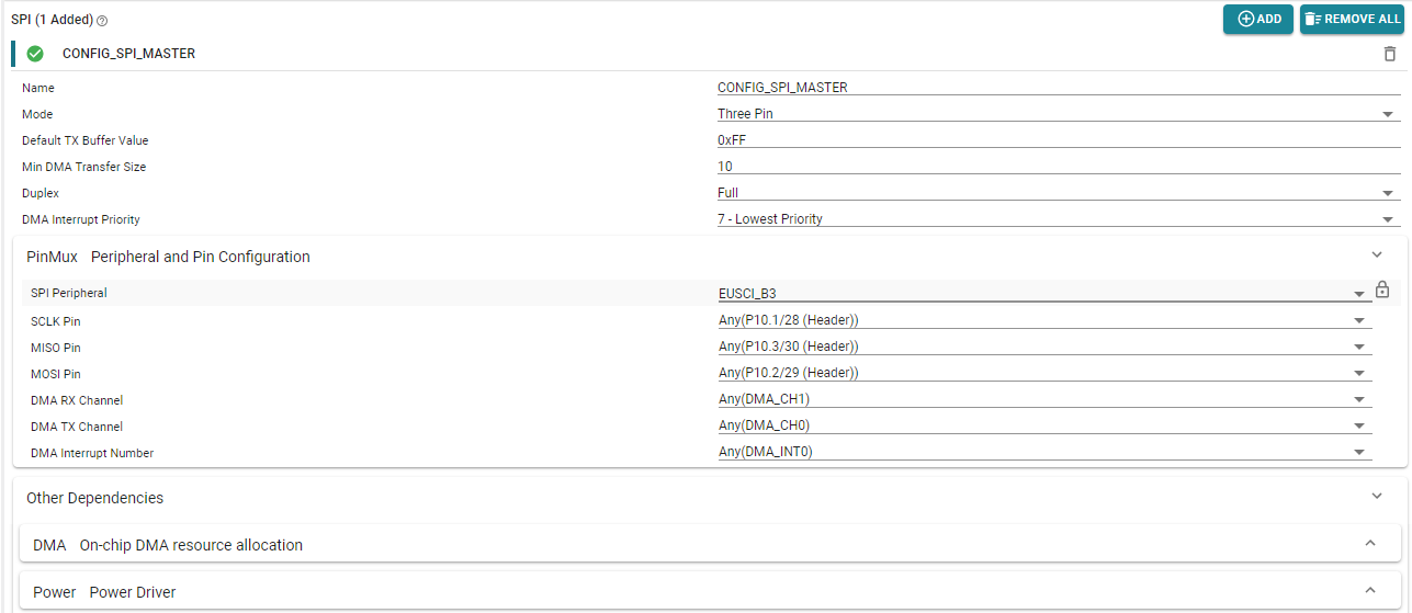
    Here a screenshot of my syscfg

    Here is my masterThread as copied from my modified example:

    void *masterThread(void *arg0)
    {
        SPI_Handle      masterSpi;
        SPI_Params      spiParams;
        SPI_Transaction transaction;
        uint32_t        i;
        bool            transferOK;
        int32_t         status;
    
        /*
         * CONFIG_SPI_MASTER_READY & CONFIG_SPI_SLAVE_READY are GPIO pins connected
         * between the master & slave.  These pins are used to synchronize
         * the master & slave applications via a small 'handshake'.  The pins
         * are later used to synchronize transfers & ensure the master will not
         * start a transfer until the slave is ready.  These pins behave
         * differently between spimaster & spislave examples:
         *
         * spimaster example:
         *     * CONFIG_SPI_MASTER_READY is configured as an output pin.  During the
         *       'handshake' this pin is changed from low to high output.  This
         *       notifies the slave the master is ready to run the application.
         *       Afterwards, the pin is used by the master to notify the slave it
         *       has opened CONFIG_SPI_MASTER.  When CONFIG_SPI_MASTER is opened, this
         *       pin will be pulled low.
         *
         *     * CONFIG_SPI_SLAVE_READY is configured as an input pin. During the
         *       'handshake' this pin is read & a high value will indicate the slave
         *       ready to run the application.  Afterwards, a falling edge interrupt
         *       will be configured on this pin.  When the slave is ready to perform
         *       a transfer, it will pull this pin low.
         *
         * Below we set CONFIG_SPI_MASTER_READY & CONFIG_SPI_SLAVE_READY initial
         * conditions for the 'handshake'.
         */
        //GPIO_setConfig(CONFIG_SPI_MASTER_READY, GPIO_CFG_OUTPUT | GPIO_CFG_OUT_LOW);
        //GPIO_setConfig(CONFIG_SPI_SLAVE_READY, GPIO_CFG_INPUT);
    
        /*
         * Handshake - Set CONFIG_SPI_MASTER_READY high to indicate master is ready
         * to run.  Wait CONFIG_SPI_SLAVE_READY to be high.
         */
        //GPIO_write(CONFIG_SPI_MASTER_READY, 1);
        //while (GPIO_read(CONFIG_SPI_SLAVE_READY) == 0) {}
    
        /* Handshake complete; now configure interrupt on CONFIG_SPI_SLAVE_READY */
        //GPIO_setConfig(CONFIG_SPI_SLAVE_READY, GPIO_CFG_IN_PU | GPIO_CFG_IN_INT_FALLING);
        //GPIO_setCallback(CONFIG_SPI_SLAVE_READY, slaveReadyFxn);
        //GPIO_enableInt(CONFIG_SPI_SLAVE_READY);
    
        /*
         * Create synchronization semaphore; the master will wait on this semaphore
         * until the slave is ready.
         */
        //status = sem_init(&masterSem, 0, 0);
        //if (status != 0) {
        //    Display_printf(display, 0, 0, "Error creating masterSem\n");
    
        //    while(1);
        //}
    
        /* Open SPI as master (default) */
        SPI_Params_init(&spiParams);
        spiParams.frameFormat = SPI_POL0_PHA1;
        spiParams.bitRate = 10000000;
        masterSpi = SPI_open(CONFIG_SPI_MASTER, &spiParams);
        if (masterSpi == NULL) {
            Display_printf(display, 0, 0, "Error initializing master SPI\n");
            while (1);
        }
        else {
            Display_printf(display, 0, 0, "Master SPI initialized\n");
        }
    
        /*
         * Master has opened CONFIG_SPI_MASTER; set CONFIG_SPI_MASTER_READY high to
         * inform the slave.
         */
        //GPIO_write(CONFIG_SPI_MASTER_READY, 0);
    
        /* Copy message to transmit buffer */
        strncpy((char *) masterTxBuffer, MASTER_MSG, SPI_MSG_LENGTH);
    
        for (i = 0; i < MAX_LOOP; i++) {
            /*
             * Wait until slave is ready for transfer; slave will pull
             * CONFIG_SPI_SLAVE_READY low.
             */
            //sem_wait(&masterSem);
    
            /* Initialize master SPI transaction structure */
            masterTxBuffer[sizeof(MASTER_MSG) - 1] = (i % 10) + '0';
            memset((void *) masterRxBuffer, 0, SPI_MSG_LENGTH);
            transaction.count = SPI_MSG_LENGTH;
            transaction.txBuf = (void *) masterTxBuffer;
            transaction.rxBuf = (void *) masterRxBuffer;
    
            /* Toggle user LED, indicating a SPI transfer is in progress */
            GPIO_toggle(CONFIG_GPIO_LED_1);
    
            /* Perform SPI transfer */
            transferOK = SPI_transfer(masterSpi, &transaction);
            if (transferOK) {
                Display_printf(display, 0, 0, "Master received: %s", masterRxBuffer);
            }
            else {
                Display_printf(display, 0, 0, "Unsuccessful master SPI transfer");
            }
    
            /* Sleep for a bit before starting the next SPI transfer  */
            usleep(3000);
        }
    
        SPI_close(masterSpi);
    
        /* Example complete - set pins to a known state */
        //GPIO_disableInt(CONFIG_SPI_SLAVE_READY);
        //GPIO_setConfig(CONFIG_SPI_SLAVE_READY, GPIO_CFG_OUTPUT | GPIO_CFG_OUT_LOW);
        //GPIO_write(CONFIG_SPI_MASTER_READY, 0);
    
        Display_printf(display, 0, 0, "\nDone");
    
        return (NULL);
    }

    //~~~~~~~~~~~~~~~~~~~~~~~~~~~~~~~~~~~~~~~~~~~~~~~~~~~~~~~~~~~~~~~~~~~~~~~~~~~~~~~~~~~~~

    Just so you are aware I also opened a trouble ticket with TI support where I sent the whole project.   Though I suspect you should be able to reproduce the condition just by changing Syscfg in the original project

    Thanks,

    Avery

  • Hi Avery,

    Thanks for sharing the additional details and especially the screenshots. It really helps debugging issues like this!

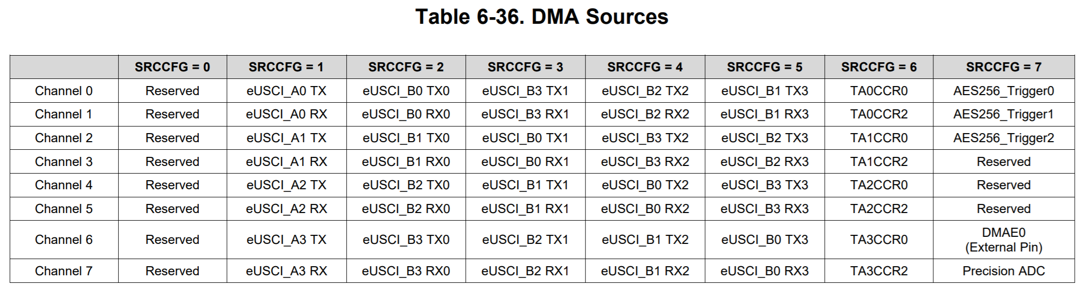
    I think I understand why this is happening. Looking at Table 6-36 from the datasheet, you'll notice there are TX, TX0, TX1, TX2 and TX3 sources. The same applies for RX. The DMA sources that end with 1, 2 and 3 only apply to the I2C mode which supports 4 different slave addresses. When using SPI or UART, only the DMA sources such as TX/RX and TX0/RX0 are applicable.

    In SysConfig, can you try changing the following parameters and see if the code works? Keep SPI Peripheral = EUSCI_B3.

    • DMA RX Channel = DMA_CH7
    • DMA TX Channel = DMA_CH6
    • DMA Interrupt Number = DMA_INT2 (see comments below)

    For the DMA Interrupt Number, you may want to use an interrupt other than DMA_INT0 since it's mapped to the logical OR of all completion events except those that are already mapped to DMA_INT1, DMA_INT2, or DMA_INT3 according to Section 6.5.2 in the Technical Reference Manual.

    Regards,

    James

  • James,

    That was it.  Its working great now.  I looked at this table earlier and tried changing the DMA channels, but I chose poorly.

    Thanks,

    Avery

  • Hi Avery,

    That's great! Thanks for letting us know. The numbers appended to the end of the TX or RX aren't clearly defined in the table so don't feel badly about your initial choice. Have a great day.

    Regards,

    James