This thread has been locked.

If you have a related question, please click the "Ask a related question" button in the top right corner. The newly created question will be automatically linked to this question.

TMS570LS0714: I2C launchpad XL2-TMS57012

Part Number: TMS570LS0714
Other Parts Discussed in Thread: TMS570LS1224, HALCOGEN

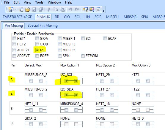
I am trying to I2C communicate a launchpad TMS570LS12x as a master and an arduino as a slave. I am using the sample code above, they are just example. I am using pin 9 and 10 of J6 of the launchpad for I2C communication and A4 and A5 on arduino fot SDA and SCL.  They do not communicate, Seems to be a launchpad programming problem because due to the two pull up resistors, I always see 3.3V in bouth lines with the oscilloscope. Moreover, using the CCS debbugging, I go into an infinite loop when I try to send data from Launchpad to Arduino. I would like to ask if I should select wich I2C port I have to use in the launchpad as there are 2 I2c port, and how I do it. I think I should not define registers as I am using halchogen library, but should I define some register for I2C? What could be the problem on having always high signal on I2C line and going in an infinite loop?

Arduino:

// Wire Slave Receiver
// by Nicholas Zambetti <<a href="www.zambetti.com>">http:/.../a>

// Demonstrates use of the Wire library
// Receives data as an I2C/TWI slave device
// Refer to the "Wire Master Writer" example for use with this

// Created 29 March 2006

// This example code is in the public domain.


#include <Wire.h>

void setup()
{
  Wire.begin(4);                // join i2c bus with address #4
  Wire.onReceive(receiveEvent); // register event
  Serial.begin(9600);           // start serial for output
}

void loop()
{
  delay(100);
}

// function that executes whenever data is received from master
// this function is registered as an event, see setup()
void receiveEvent(int howMany)
{
  while(1 < Wire.available()) // loop through all but the last
  {
    char c = Wire.read(); // receive byte as a character
    Serial.print(c);         // print the character
  }
  int x = Wire.read();    // receive byte as an integer
  Serial.println(x);         // print the integer
}

Launchpad:

/** @file sys_main.c 
*   @brief Application main file
*   @date 17.Nov.2014
*   @version 04.02.00
*
*   This file contains an empty main function,
*   which can be used for the application.
*/

/* 
* Copyright (C) 2009-2014 Texas Instruments Incorporated - <a href="www.ti.com/.../a> 
* 
* 
*  Redistribution and use in source and binary forms, with or without 
*  modification, are permitted provided that the following conditions 
*  are met:
*
*    Redistributions of source code must retain the above copyright 
*    notice, this list of conditions and the following disclaimer.
*
*    Redistributions in binary form must reproduce the above copyright
*    notice, this list of conditions and the following disclaimer in the 
*    documentation and/or other materials provided with the   
*    distribution.
*
*    Neither the name of Texas Instruments Incorporated nor the names of
*    its contributors may be used to endorse or promote products derived
*    from this software without specific prior written permission.
*
*  THIS SOFTWARE IS PROVIDED BY THE COPYRIGHT HOLDERS AND CONTRIBUTORS 
*  "AS IS" AND ANY EXPRESS OR IMPLIED WARRANTIES, INCLUDING, BUT NOT 
*  LIMITED TO, THE IMPLIED WARRANTIES OF MERCHANTABILITY AND FITNESS FOR
*  A PARTICULAR PURPOSE ARE DISCLAIMED. IN NO EVENT SHALL THE COPYRIGHT 
*  OWNER OR CONTRIBUTORS BE LIABLE FOR ANY DIRECT, INDIRECT, INCIDENTAL, 
*  SPECIAL, EXEMPLARY, OR CONSEQUENTIAL DAMAGES (INCLUDING, BUT NOT 
*  LIMITED TO, PROCUREMENT OF SUBSTITUTE GOODS OR SERVICES; LOSS OF USE,
*  DATA, OR PROFITS; OR BUSINESS INTERRUPTION) HOWEVER CAUSED AND ON ANY
*  THEORY OF LIABILITY, WHETHER IN CONTRACT, STRICT LIABILITY, OR TORT 
*  (INCLUDING NEGLIGENCE OR OTHERWISE) ARISING IN ANY WAY OUT OF THE USE 
*  OF THIS SOFTWARE, EVEN IF ADVISED OF THE POSSIBILITY OF SUCH DAMAGE.
*
*/


/* USER CODE BEGIN (0) */
/* USER CODE END */

/* Include Files */

#include "sys_common.h"

/* USER CODE BEGIN (1) */
#include "i2c.h"
/* USER CODE END */

/** @fn void main(void)
*   @brief Application main function
*   @note This function is empty by default.
*
*   This function is called after startup.
*   The user can use this function to implement the application.
*/

/* USER CODE BEGIN (2) */
#define DATA_COUNT  10

#define Master_Address 0x26
#define Slave_Address  0x4

uint8_t TX_Data_Master[10] = { 0x10,0x11,0x12,0x13,0x14,0x15,0x16,0x17,0x18,0x19};
uint8_t RX_Data_Master[10] = { 0 };

uint8_t TX_Data_Slave[10] = { 0x20,0x21,0x22,0x23,0x24,0x25,0x26,0x27,0x28,0x29};
uint8_t RX_Data_Slave[10] = { 0 };

/* USER CODE END */

void main(void)
{
/* USER CODE BEGIN (3) */

    int repeat = 0; int delay =0;

///////////////////////////////////////////////////////////////
//        Master Transfer Functionality                      //
///////////////////////////////////////////////////////////////
    /* I2C Init as per GUI
     *  Mode = Master - Transmitter
     *  baud rate = 100KHz
     *  Count = 10
     *  Bit Count = 8bit
     */
    i2cInit();

    /* Configure address of Slave to talk to */
    i2cSetSlaveAdd(i2cREG1, Slave_Address);

    /* Set direction to Transmitter */
    /* Note: Optional - It is done in Init */
    i2cSetDirection(i2cREG1, I2C_TRANSMITTER);


    for(repeat = 0; repeat < 2; repeat++)
    {
        /* Configure Data count */
        /* Note: Optional - It is done in Init, unless user want to change */
        i2cSetCount(i2cREG1, DATA_COUNT);

        /* Set mode as Master */
        i2cSetMode(i2cREG1, I2C_MASTER);

        /* Set Stop after programmed Count */
        i2cSetStop(i2cREG1);

        /* Transmit Start Condition */
        i2cSetStart(i2cREG1);

        /* Tranmit DATA_COUNT number of data in Polling mode */
        i2cSend(i2cREG1, DATA_COUNT, TX_Data_Master);

        /* Wait until Bus Busy is cleared */
        while(i2cIsBusBusy(i2cREG1) == true);

        /* Wait until Stop is detected */
        while(i2cIsStopDetected(i2cREG1) == 0);

        /* Clear the Stop condition */
        i2cClearSCD(i2cREG1);

        /* Simple Dealya before starting Next Block */
        /* Depends on how quick the Slave gets ready */
        for(delay=0;delay<1000000;delay++);

    }

  • Hello,

    This device has only 1 I2C module. Since the I2C signals are open-drain/open-collect signals, the I2C signals should be pulled up to 3.3V. When the bus is free, both pins are high.

    When running 

            /* Transmit Start Condition */
            i2cSetStart(i2cREG1);
    you should see the start bit, and the slave address on I2C SDA line. I have no idea about the code in your I2V slave side. 
  • Thank you for the answer Wang. I have defined the slave address as 0x4 in CCS and as Wire.begin(4); in arduino. Could you explain me better how to define the start bit? where can i find documentacion about? In the reg_i2c library it is defined as:
    #define i2cREG1 ((i2cBASE_t *)0xFFF7D400U)
    In the datasheet od TMS570LS1224 section 8.6 I fuond some ID, I don't know if I should find the start bit there. 

    Bouth lines (SDA, SCL) are pulled up to 3.3 V with two 1k resistors. 
    The code on the slave is just an arduino example wich just ptint what receive from the master. It is just for test the communication. 

  • Hello,

    In master mode, setting STT bit of I2CDMR register to 1 generates a START condition.

    Start condition: is defined as a high-to-low transition on the SDA line while SCL is high.

  • Sorry, I am not finding the bit and register you are talking of. I have looked at reg_i2c.h, i2c.h and i2c.c. Can you tell me where they are?

    I am using the function i2cSetStart(i2cREG1); as defined in Halcogen. Where the function is defined like this in i2c.c:

    void i2cSetStart(i2cBASE_t *i2c)
    {
    /* USER CODE BEGIN (7) */
    /* USER CODE END */

    i2c->MDR |= (uint32)I2C_START_COND; /* set start condition */

    /* USER CODE BEGIN (8) */
    /* USER CODE END */
    }

    And in i2c.h:

    I2C_START_COND  = 0x2000U,  /* In Master Mode only */

  • Yes, i2cSetStart() will generate the start condition. I2C->MDR represents the I2CMDR register listed in TRM:

  • The funtion i2cSetStart() seems to work right. The register change from:

    Name : i2c->MDR
    Default:3616
    Hex:0x00000E20
    Decimal:3616
    Octal:07040
    Binary:00000000000000000000111000100000b

    to:

    Name : i2c->MDR
    Default:11808
    Hex:0x00002E20
    Decimal:11808
    Octal:027040
    Binary:00000000000000000010111000100000b

    But I still can't see any signal on the i2c lines with the oscilloscope.

    Even if the slave was wrong, shouldn't I see even a CLK signal sent from the Launchpad to the slave?

  • I am not understanding if the launchpad is working correctly. If I use the code to toggle a led it works.

    gioToggleBit(gioPORTB, 1);
    for (;;) { gioToggleBit(gioPORTB, 1);
    for (i = 0; i < DELAY_VALUE; i++); }

    If I try to put high a GIO it doesn't:

    gioSetBit(gioPORTB,3,1);
    gioSetBit(gioPORTA,0,1);
    gioSetBit(gioPORTA,1,1);

    When I check with the oscilloscpe:

    J5 pin 4: GIOB_3

    J4 pin 9: GIOB_1

    J4 pin 10: GIOB_0

    This is the whole code I am using just to try if the launchpad is working:

    /* Include Files */
    
    #include "sys_common.h"
    
    /* USER CODE BEGIN (1) */
    #include "i2c.h"
    #include "gio.h"
    #include "reg_i2c.h"
    #include "reg_gio.h"
    #include "can.h"
    #include "reg_het.h"
    #include "reg_mibspi.h"
    /* USER CODE END */
    
    /** @fn void main(void)
    *   @brief Application main function
    *   @note This function is empty by default.
    *
    *   This function is called after startup.
    *   The user can use this function to implement the application.
    */
    
    /* USER CODE BEGIN (2) */
    #define DATA_COUNT  10
    
    #define Master_Address 0x26
    #define Slave_Address  0x04
    
    uint8_t TX_Data_Master[10] = { 0x10,0x11,0x12,0x13,0x14,0x15,0x16,0x17,0x18,0x19};
    uint8_t RX_Data_Master[10] = { 0 };
    
    uint8_t TX_Data_Slave[10] = { 0x20,0x21,0x22,0x23,0x24,0x25,0x26,0x27,0x28,0x29};
    uint8_t RX_Data_Slave[10] = { 0 };
    
    /* USER CODE BEGIN (2) */
    #define DELAY_VALUE 1000000
    /* USER CODE END */
    
    /*
    i2c->MDR |= (uint32)I2C_START_COND;  /* set start condition */
    /*
    canREG3->TIOC =  (uint32)((uint32)1U  << 18U )
                   | (uint32)((uint32)1U  << 17U )
                   | (uint32)((uint32)0U  << 16U )
                   | (uint32)((uint32)0U  << 3U )
                   | (uint32)((uint32)1U  << 2U )
                   | (uint32)((uint32)1U << 1U );
    */
    
    
    int main(void)
    {
    /* USER CODE BEGIN (3) */
        int i;
    
        gioInit();
    
        gioSetBit(gioPORTB,3,1);
        gioSetBit(gioPORTA,0,1);
        gioSetBit(gioPORTA,1,1);


        gioToggleBit(gioPORTB, 1);
          for (;;) { gioToggleBit(gioPORTB, 1);
          for (i = 0; i < DELAY_VALUE; i++); }
    /* USER CODE END */
        int repeat = 0; int delay =0;
    
     ///////////////////////////////////////////////////////////////
     //        Master Transfer Functionality                      //
     ///////////////////////////////////////////////////////////////
         /* I2C Init as per GUI
          *  Mode = Master - Transmitter
          *  baud rate = 100KHz
          *  Count = 10
          *  Bit Count = 8bit
          */
         i2cInit();
         /* Set mode as Master */
         i2cSetMode(i2cREG1, I2C_MASTER);
         /* Transmit Start Condition */
        // i2c->MDR = (uint32)((uint32)1U << 13U );
         i2cSetStart(i2cREG1);
    
         /* Configure address of Slave to talk to */
         i2cSetSlaveAdd(i2cREG1, Slave_Address);
    
         /* Set direction to Transmitter */
         /* Note: Optional - It is done in Init */
         i2cSetDirection(i2cREG1, I2C_TRANSMITTER);
    
         /* Set mode as Master */
         i2cSetMode(i2cREG1, I2C_MASTER);
    
    
         for(repeat = 0; repeat < 2; repeat++)
         {
             /* Configure Data count */
             /* Note: Optional - It is done in Init, unless user want to change */
             i2cSetCount(i2cREG1, DATA_COUNT);
    
             /* Set mode as Master */
             //i2cSetMode(i2cREG1, I2C_MASTER);
    
             /* Set Stop after programmed Count */
             //i2cSetStop(i2cREG1);
    
             /* Transmit Start Condition */
            // i2c->MDR = (uint32)((uint32)1U << 13U );
             i2cSetStart(i2cREG1);
             //i2c->MDR = (uint32)((uint32)1U << 13U );
    
             /* Tranmit DATA_COUNT number of data in Polling mode */
             i2cSend(i2cREG1, DATA_COUNT, TX_Data_Master);
    
             /* Wait until Bus Busy is cleared */
             while(i2cIsBusBusy(i2cREG1) == true);
    
             /* Wait until Stop is detected */
             while(i2cIsStopDetected(i2cREG1) == 0);
    
             /* Clear the Stop condition */
             i2cClearSCD(i2cREG1);
    
             /* Simple Dealya before starting Next Block */
             /* Depends on how quick the Slave gets ready */
             for(delay=0;delay<1000000;delay++);
    
         }
        return 0;
    }
    
    
    /* USER CODE BEGIN (4) */
    /* USER CODE END */


    Can you also confirm me that SCL is the pin8 J11 and SDA pin 9 J11?

  • You can use either pin8/9 on J5 or Pin8/9 on J11. 

    The device pin 3/4 used by I2C, MibSPI and N2HET. Please configure the pinmux properly to use those pins for I2C.

  • Thank you so much for the answer, but how can I configure pins 3/4 as I2C?

  • This was the problem. Now I can communicate the TI as a master with an arduino as slave.

    I have another problem now. If I send:

    i2cSend(i2cREG1, DATA_COUNT, TX_Data_Master );

    where:

    uint8_t TX_Data_Master[10] = { 0xFF,0x00,0xFF,0x00,0x55,0x55,0x55,0x55,0x18,0x19};

    I see correctly the bits with the oscilloscope. When I try to pass an uint32 because I have 32 bits, it try to communicate sending some bits but then the value of SDA stay at 3.3V and the value of SCL stay at 0V. 
    I tryed to pass the value of the variable "muestra32" into a 8 bits value using:
        uint8_t buffer1=buffer>>24;
        uint8_t buffer2=buffer>>16;
        uint8_t buffer3=buffer>>8;
        uint8_t buffer4=buffer;
       /* Configure Data count */

               /* Set Stop after programmed Count */
               i2cSetStop(i2cREG1);

               /* Transmit Start Condition */
               i2cSetStart(i2cREG1);

               /* Tranmit DATA_COUNT number of data in Polling mode */
               i2cSend(i2cREG1, DATA_COUNT, buffer1);
               i2cSend(i2cREG1, DATA_COUNT, buffer2);
               i2cSend(i2cREG1, DATA_COUNT, buffer3);
               i2cSend(i2cREG1, DATA_COUNT, buffer4);
    But it still doesn't work. Maybe I am not converting correctly the value of the 32 bits into a 8 bits. How should i do that?
    In the last case, it send the buffer1, then SDA stay at 3.3V and SCL at 0V, I sends the buffer2, It sends anothe package and finally SDA and SCL stay at 3.3V. The other 2 buffer can't be sent.
  • Hello,

    uint32_t b[10];

    uint8_t a[40];

    for(i=0; i<10; i++){

         a[i*4+0] = (b[i] & 0xFF000000)  >> 24;

         a[i*4+1] = (b[i] & 0x00FF0000) >> 16;

        a[i*4+2] = (b[i] & 0x0000FF00) >> 8;

     a[i*4+3] = (b[i] & 0x000000FF);
    }

    data_count=40
     i2cSetCount(i2cREG1, data_count);
    ...
    i2cSend(i2cREG1, data_count, &a[0]);


    Please read the I2C chapter for using I2C protocol.
  • Thank you, it seems to work better, I have to do an additional check. But I have another question. I would like to set a delay of 10 ms using a 16MHz clock. 

    Reading the TRM section 11.4 I set:

    dccSetCounter0Seed(dccREG1, DCC_settling_delay); //delay of 10 ms for freq 16Mhz as explained in TRM section 11.4 for dccREG1
    dccEnable(dccREG1);

    Where DCC_settling_delay=160000;  (10 ms x 16Mhz).

    I even tried to set the register valid0 as 4 which is the minimum value possible for this register and to define uint32 DCC_settling_delay=159996; (160000-4) but it doesn't work.

    uint32 tolerance=4;
    dccEnable(dccREG1);
    dccSetTolerance(dccREG1, tolerance);

    In addition, I have the Stat register as 0x00000001 which should mean it has sent a flag but there is an error.

    Finally, how can I check or wait if the 10 ms has passed? Which register should go from 160000 to 0? 

  • It is not working correctly. I have the function:

    void write_slave(int address, int buffer){
    
        uint32_t b[10]=buffer;
        uint8_t a[40];
        int i=0;
        for(i=0; i<10; i++){
             a[i*4+0] = (b[i] & 0xFF000000)  >> 24;
             a[i*4+1] = (b[i] & 0x00FF0000) >> 16;
             a[i*4+2] = (b[i] & 0x0000FF00) >> 8;
             a[i*4+3] = (b[i] & 0x000000FF);
        }
    
        //uint8_t TX_Data_Master[4] = { 0xFF,0x00,0xFF,0x00};
    
               /* Set Stop after programmed Count */
               i2cSetStop(i2cREG1);
    
               /* Transmit Start Condition */
               i2cSetStart(i2cREG1);
    
               /* Tranmit DATA_COUNT number of data in Polling mode */
               i2cSend(i2cREG1, DATA_COUNT, &a[0]);
               //i2cSend(i2cREG1, DATA_COUNT, TX_Data_Master);
               /* Wait until Bus Busy is cleared */
               while(i2cIsBusBusy(i2cREG1) == true);
               /* Wait until Stop is detected */
               while(i2cIsStopDetected(i2cREG1) == 0);
    
               /* Set Stop after programmed Count */
               i2cSetStop(i2cREG1);
               /* Clear the Stop condition */
               i2cClearSCD(i2cREG1);
    }

    It doesn't go out from i2cSend function. Meanwhile if I send i2cSend(i2cREG1, DATA_COUNT, TX_Data_Master); where uint8_t TX_Data_Master[4] = { 0xFF,0x00,0xFF,0x00}; it works correctly. I change the DATA_COUNT form 4 (case TX_Data_Master) to 40 (case &a[0]). 

  • For TX_Data_Master[4] = { 0xFF,0x00,0xFF,0x00}, I2CSend() works. There is no problem with the function. You can use the same DATA_COUNT to send a[x].

  • Thank you for your help, I have one last problem I think, I never see the stop condition, in any case, so when the master ends to send the data, SDL and SCL stay at 0V, when they should go both to 3.3V. Even if I send: i2cSetStop(i2cREG1); the lines stays at 0V. So the code stay in while(i2cIsBusBusy(i2cREG1) == true); until it passes some time and it detects the free bus and goes out from the while loop. 

  • I have this function into a loop:

    void write_slave(int address, int buffer){

    uint8_t TX_Data_Master[4] = { 0xFF,0x00,0xFF,0x00};

    /* Set Stop after programmed Count */
    i2cSetStop(i2cREG1);

    /* Transmit Start Condition */
    i2cSetStart(i2cREG1);

    /* Tranmit DATA_COUNT number of data in Polling mode */
    i2cSend(i2cREG1, DATA_COUNT, TX_Data_Master);

    /* Set Stop after programmed Count */
    i2cSetStop(i2cREG1);

    /* Wait until Bus Busy is cleared */
    while(i2cIsBusBusy(i2cREG1) == true);

    /* Wait until Stop is detected */
    while(i2cIsStopDetected(i2cREG1) == 0);

    /* Set Stop after programmed Count */
    i2cSetStop(i2cREG1);

    /* Clear the Stop condition */
    i2cClearSCD(i2cREG1);
    }

    The first time it runs the loop I can see the data sent with the oscilloscope. But sending i2cSend(i2cREG1, DATA_COUNT, TX_Data_Master); I do not see the stop bit (SCL and SDA at 3.3V, they stay at 0V) I just see the data; when the loop goes into the second run, so the  write_slave function is executed for the second time, the lines SDA and SCl stays at 3.3V and the i2cSetStart(i2cREG1); so doesn't work. the i2cSend(i2cREG1, DATA_COUNT, TX_Data_Master); doesen't work as well and it goes into an infinte loop in the i2c.c: 

    /*SAFETYMCUSW 28 D MR:NA <APPROVED> "Potentially infinite loop found - Hardware Status check for execution sequence" */
    while ((i2c->STR & (uint32)I2C_TX_INT) == 0U)
    {
    } /* Wait */

  • I have this function into a loop:

    void write_slave(int address, int buffer){uint8_t TX_Data_Master[4] = { 0xFF,0x00,0xFF,0x00,0xFF,0x00,0xFF,0x00,0xFF,0x00};

    i2cSetStop(i2cREG1);

    /* Transmit Start Condition */
    i2cSetStart(i2cREG1);

    i2cSend(i2cREG1, DATA_COUNT, TX_Data_Master);

    i2cSetStop(i2cREG1);

    while(i2cIsBusBusy(i2cREG1) == true);

    while(i2cIsStopDetected(i2cREG1) == 0);

    i2cSetStop(i2cREG1);

    i2cClearSCD(i2cREG1);
    }

    In the main function are defined:

    #define DATA_COUNT 10  

    i2cSetSlaveAdd(i2cREG1, SLAVE_WRITE_ADDR);

    i2cSetDirection(i2cREG1, I2C_TRANSMITTER);
    i2cSetCount(i2cREG1, DATA_COUNT);
    i2cSetMode(i2cREG1, I2C_MASTER);

    The first time I run the code I can see correctly the data in the oscilloscope:

    But the second time I send the data i2cSend(i2cREG1, DATA_COUNT, TX_Data_Master); the program goes into an infinite loop:

    /*SAFETYMCUSW 28 D MR:NA <APPROVED> "Potentially infinite loop found - Hardware Status check for execution sequence" */
    while ((i2c->STR & (uint32)I2C_TX_INT) == 0U)
    {
    } /* Wait *

    Why? How can I solve it?

  • Hi,

    1. The stop condition is generated when ICCNT passes 0 when the I2C is in non-repeat mode (RM=0).

    2. The stop condition is generated if STP bit is 1 In repeat mode (RM=1).

  • This is my code for writing data i2C EEPROM:

    /* Write to a slave device */
    int I2C_Write_M(short Slave_Add, short Write_Add, short Count, uint8 *buff )
    {
    int error, dummy; // Return code
    error = 0x00; // Default, no error

    if((i2cREG1->STR & I2C_BUSBUSY ) == 0) //test if Busy is busy
    {
    /* Set direction to Transmitter */
    i2cSetDirection(i2cREG1, I2C_TRANSMITTER);
    /* Set mode as Master */
    i2cSetMode(i2cREG1, I2C_MASTER);

    /* Clear Start bit */
    i2cREG1->MDR &= ~(I2C_START_COND);
    /* Set Stop after programmed Count */
    i2cSetStop(i2cREG1);

    /* Clear RM bit */
    i2cREG1->MDR &= ~(I2C_REPEATMODE); // Not in Repeat Mode

    /* Configure Data count */
    i2cSetCount(i2cREG1, Count+1);

    /* Configure address of Slave to talk to */
    i2cSetSlaveAdd(i2cREG1, Slave_Add);

    /* Transmit Start Condition */
    i2cSetStart(i2cREG1); //I2C Bus: Start--Slave Addr

    /* send the write address */
    i2cSendByte(i2cREG1, Write_Add); // Transmit data to Select Destination Register

    if((i2cREG1->STR & I2C_NACK) == 0) // Check for Positive Acknoledge
    {
    /* Tranmit DATA_COUNT number of data in Polling mode */
    i2cSend(i2cREG1, Count, buff);
    }
    else{
    dummy = i2cREG1->IVR; // Clear nack flag
    i2cSetStop(i2cREG1); // to generate a STOP
    error=-2; // Set error as NoAck
    }
    }
    else{
    error = -1; // Set error as Bus Busy
    }

    while((i2cREG1->MDR & I2C_STOP_COND) ==1);

    return error;
    }

  • If I use this code it works but it is just becouse I always initialize i2c, that should not be correct.

    while (1){
                 i2cInit();
             /* Configure address of Slave to talk to */
             i2cSetSlaveAdd(i2cREG1, SLAVE_WRITE_ADDR);
             /* Set direction to Transmitter */
             /* Note: Optional - It is done in Init */
             i2cSetDirection(i2cREG1, I2C_TRANSMITTER);
             /* Configure Data count */
             /* Note: Optional - It is done in Init, unless user want to change */
             i2cSetCount(i2cREG1, DATA_COUNT);
             /* Set mode as Master */
             i2cSetMode(i2cREG1, I2C_MASTER);
    
             //vTaskDelay(5000); //is t delay 5000ms
             int i=0;
             for ( i=0; i<100000; i++){
                 int c=0;
             }
             write_slave(SLAVE_WRITE_ADDR, TX_Data_Master); //Write to slave the data
            // i2cREG1->STR  = (uint32)((uint32)1U << 4U);
             //i2cREG1->STR =  (uint32)((uint32)1U  << 5U );
    
             int al=0;
             }

    In addition, I have used a for just to put a delay as the function vTaskDelay(5); it is not working as well.

    Without constantly initialize the i2cInit(); I can just sent the command once, and I can see the register STR as hex 0x410= bin 10000010000, wich means that bits RSFULL and TXREADY are high, but when I send the ccommand the second time, the register STR change to hex 0x400 = bin 10000000000, so the bit TXREADY has changed ftom high to low. Why? what is happening?


  • I assume you have solved your problem.