Part Number: TM4C1294NCPDT
Hi All,
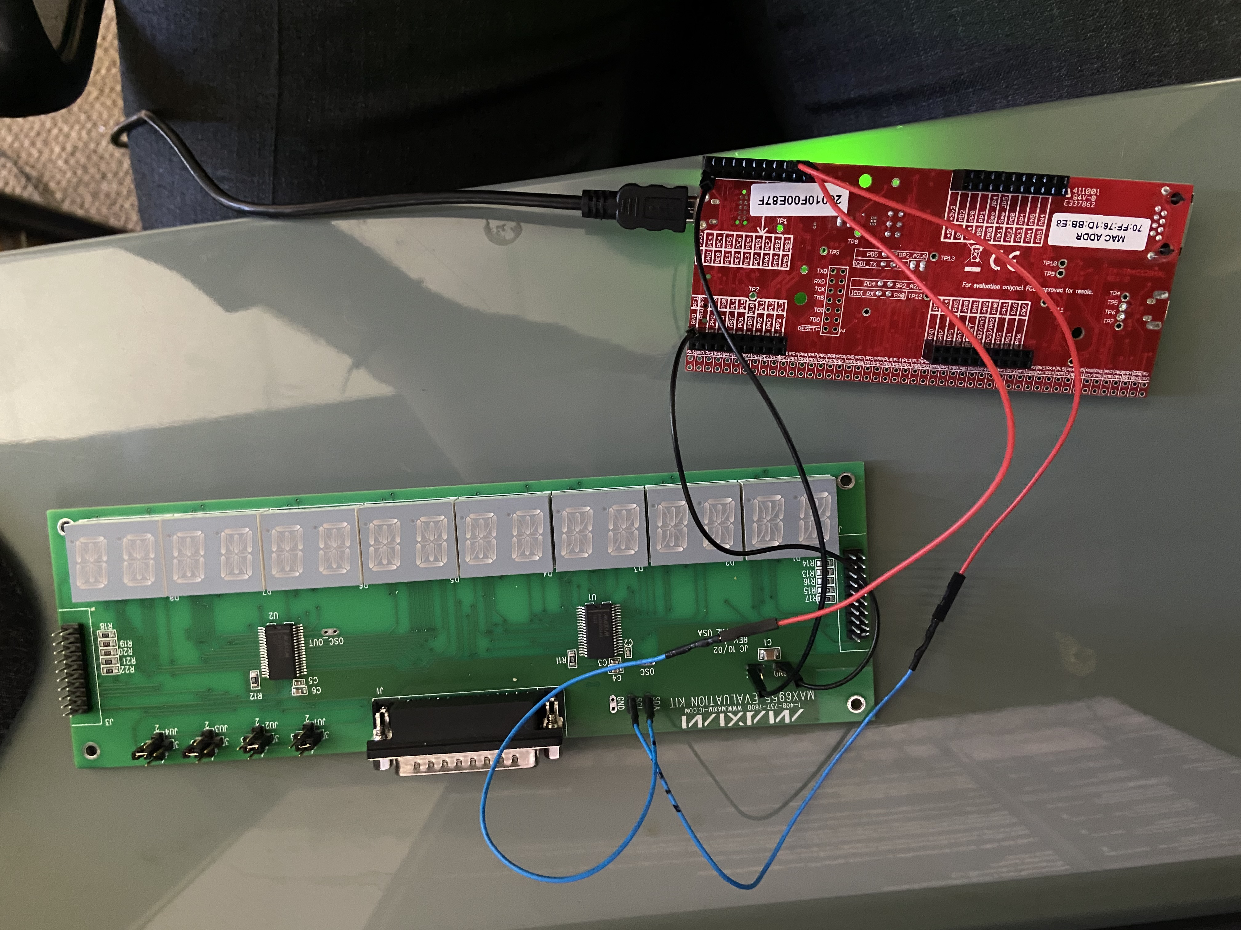
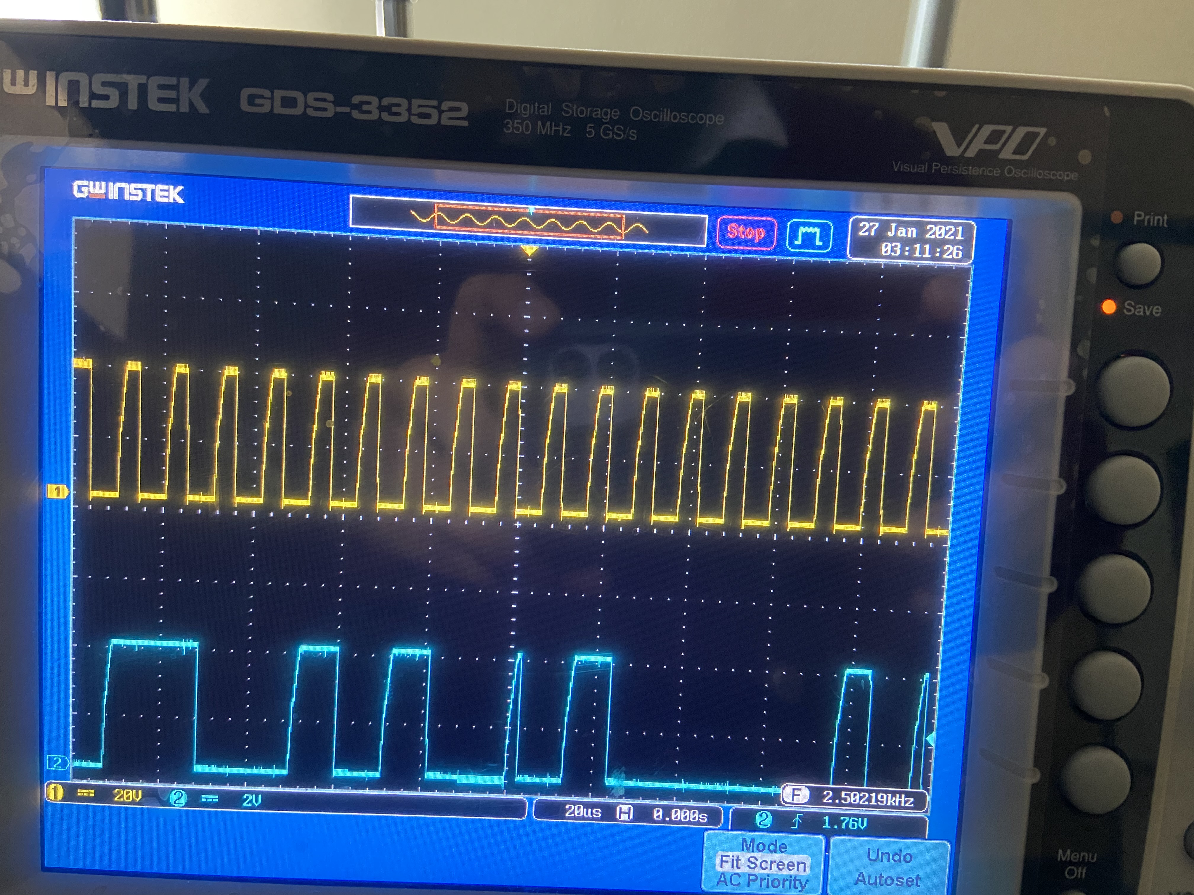
I'm trying to develop I2C protocol using TM4C1294NCPDT with PORT B and I2C0. I'm facing difficulties in sending a character byte through the SDA bus. Could you please have a look at the code snippet and give me more suggestion or advice in the application development.
#include <stdbool.h>
#include <stdint.h>
#include "inc/hw_i2c.h"
#include "inc/hw_memmap.h"
#include "inc/hw_types.h"
#include "driverlib/gpio.h"
#include "driverlib/i2c.h"
#include "driverlib/pin_map.h"
#include "driverlib/sysctl.h"
#include "driverlib/uart.h"
#include "utils/uartstdio.h"
#include "MAX6955.h"
#include "display_task.h"
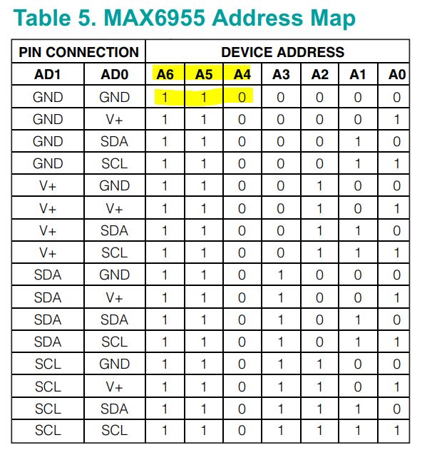
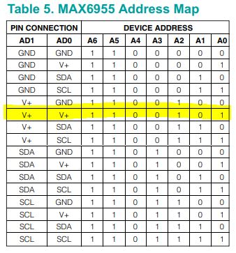
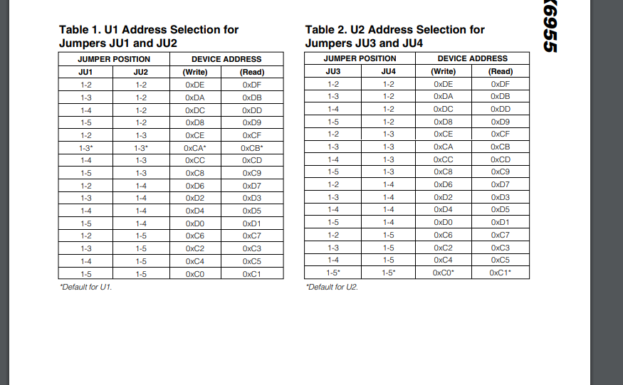
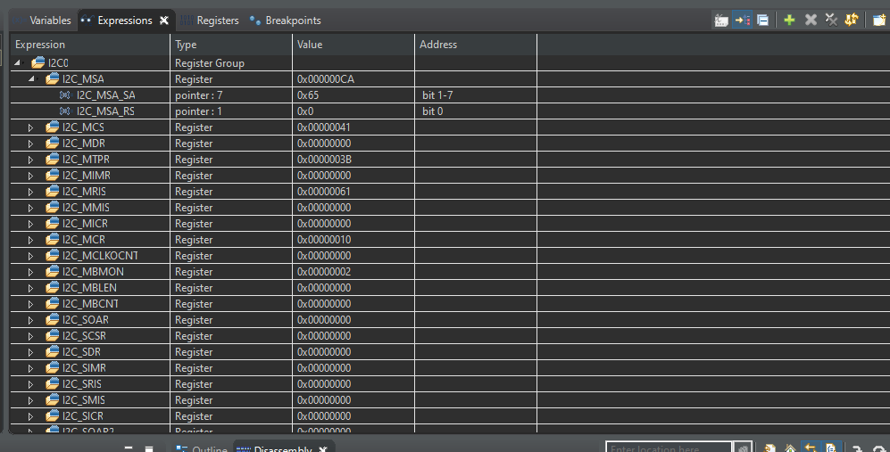
#define SLAVEADDRESS 0xCA
void I2CSendChar(uint8_t slavedeviceAddress,uint8_t deviceRegister, uint8_t deviceData)
{
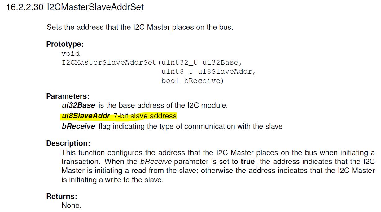
I2CMasterSlaveAddrSet(I2C0_BASE, slavedeviceAddress, false);
I2CMasterDataPut(I2C0_BASE, deviceRegister);
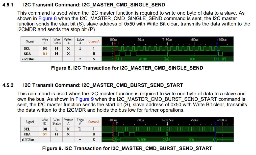
I2CMasterControl(I2C0_BASE, I2C_MASTER_CMD_BURST_SEND_START);
while(I2CMasterBusy(I2C0_BASE));
I2CMasterDataPut(I2C0_BASE, deviceData);
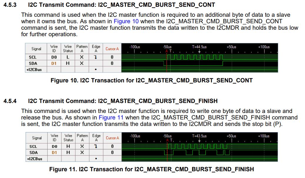
I2CMasterControl(I2C0_BASE, I2C_MASTER_CMD_BURST_SEND_FINISH);
while(I2CMasterBusy(I2C0_BASE));
}
void
InitConsole(void)
{
//
// Enable GPIO port A which is used for UART0 pins.
// TODO: change this to whichever GPIO port you are using.
//
SysCtlPeripheralEnable(SYSCTL_PERIPH_GPIOA);
//
// Configure the pin muxing for UART0 functions on port A0 and A1.
// This step is not necessary if your part does not support pin muxing.
// TODO: change this to select the port/pin you are using.
//
GPIOPinConfigure(GPIO_PA0_U0RX);
GPIOPinConfigure(GPIO_PA1_U0TX);
//
// Enable UART0 so that we can configure the clock.
//
SysCtlPeripheralEnable(SYSCTL_PERIPH_UART0);
//
// Use the internal 16MHz oscillator as the UART clock source.
//
UARTClockSourceSet(UART0_BASE, UART_CLOCK_PIOSC);
//
// Select the alternate (UART) function for these pins.
// TODO: change this to select the port/pin you are using.
//
GPIOPinTypeUART(GPIO_PORTA_BASE, GPIO_PIN_0 | GPIO_PIN_1);
//
// Initialize the UART for console I/O.
//
UARTStdioConfig(0, 115200, 16000000);
}
int
main(void)
{
uint32_t ui32SysClock;
// Set the clocking to run directly from the external crystal/oscillator.
ui32SysClock = SysCtlClockFreqSet((SYSCTL_XTAL_25MHZ |
SYSCTL_OSC_MAIN |
SYSCTL_USE_OSC), 25000000);
// The I2C0 peripheral must be enabled before use.
SysCtlPeripheralEnable(SYSCTL_PERIPH_I2C0);
// GPIO port B needs to be enabled so these pins can
SysCtlPeripheralEnable(SYSCTL_PERIPH_GPIOB);
GPIOPinConfigure(GPIO_PB2_I2C0SCL);
GPIOPinConfigure(GPIO_PB3_I2C0SDA);
// GPIO pins pins for I2C operation, setting them to
// open-drain operation with weak pull-ups.
//
GPIOPinTypeI2CSCL(GPIO_PORTB_BASE, GPIO_PIN_2);
GPIOPinTypeI2C(GPIO_PORTB_BASE, GPIO_PIN_3);
I2CMasterEnable(I2C0_BASE);
HWREG(I2C0_BASE + I2C_O_MCR) |= 0x10;
//
// Enable and initialize the I2C0 master module. Use the system clock for
// the I2C0 module. The last parameter sets the I2C data transfer rate.
// If false the data rate is set to 100kbps and if true the data rate will
// be set to 400kbps. For this example we will use a data rate of 100kbps.
//
I2CMasterInitExpClk(I2C0_BASE, ui32SysClock, false);
InitConsole();
//
I2CMasterSlaveAddrSet(I2C0_BASE, SLAVEADDRESS, false);
UARTprintf("The slave address: %X\n", SLAVEADDRESS);
// initMAX6955();
while(1){
I2CSendChar(SLAVEADDRESS, reg_digit0, 0x4D);
I2CSendChar(SLAVEADDRESS, reg_digit1, 0x41);
I2CSendChar(SLAVEADDRESS, reg_digit2, 0x58);
I2CSendChar(SLAVEADDRESS, reg_digit3, 0x49);
I2CSendChar(SLAVEADDRESS, reg_digit4, 0x4D);
I2CSendChar(SLAVEADDRESS, reg_digit5, 0x2D);
I2CSendChar(SLAVEADDRESS, reg_digit4, 0x49);
I2CSendChar(SLAVEADDRESS, reg_digit5, 0x43);
}
}
Thanks and Regards,
Sai Santha