Part Number: EK-TM4C1294XL
I have a program sending a 16-bit word out on 3 ports like this:
void CGsendData(unsigned short Data)
{
    GPIOPinWrite(GPIO_PORTA_BASE,0xFF,0xf7);//Data & 0x00FF);
    GPIOPinWrite(GPIO_PORTD_BASE,0x0F,(Data >> 8) & 0x0F);
    GPIOPinWrite(GPIO_PORTC_BASE,0xF0,(Data >> 8) & 0xF0);

    TimerEnable(TIMER3_BASE, TIMER_A); //Start timer for setting DC
}
Temporarily I have changed the data put out on PortA, I will return to that.
My ports are initialized as this:
    SysCtlPeripheralEnable(SYSCTL_PERIPH_GPIOQ);

    //Enable using ports
    SysCtlPeripheralEnable(SYSCTL_PERIPH_GPIOA);
    SysCtlPeripheralEnable(SYSCTL_PERIPH_GPIOB);
    SysCtlPeripheralEnable(SYSCTL_PERIPH_GPIOC);
    SysCtlPeripheralEnable(SYSCTL_PERIPH_GPIOD);
    SysCtlPeripheralEnable(SYSCTL_PERIPH_GPIOE);
    SysCtlPeripheralEnable(SYSCTL_PERIPH_GPIOF);
    SysCtlPeripheralEnable(SYSCTL_PERIPH_GPIOG);
    SysCtlPeripheralEnable(SYSCTL_PERIPH_GPIOH);
    SysCtlPeripheralEnable(SYSCTL_PERIPH_GPIOK);
    SysCtlPeripheralEnable(SYSCTL_PERIPH_GPIOL);
    SysCtlPeripheralEnable(SYSCTL_PERIPH_GPIOM);
    SysCtlPeripheralEnable(SYSCTL_PERIPH_GPION);
    SysCtlPeripheralEnable(SYSCTL_PERIPH_GPIOP);
    SysCtlPeripheralEnable(SYSCTL_PERIPH_GPIOQ);

    //Output ports
    GPIOPinTypeGPIOOutput(GPIO_PORTA_BASE, 0xFF); //All Port A as output
    GPIOPinTypeGPIOOutput(GPIO_PORTK_BASE, 0xFF); //All Port K as output
    GPIOPinTypeGPIOOutput(GPIO_PORTM_BASE, 0xFF); //All Port M as output

    GPIOPinTypeGPIOOutput(GPIO_PORTB_BASE, 0x3C); //Port B 2-5 as output
    GPIOPinTypeGPIOOutput(GPIO_PORTC_BASE, 0xF0); //Port C 4-7 as output
    GPIOPinTypeGPIOOutput(GPIO_PORTD_BASE, 0x0F); //Port D 0-3 as output
    GPIOPinTypeGPIOOutput(GPIO_PORTF_BASE, 0x06); //Port F 1-2 as output
    GPIOPinTypeGPIOOutput(GPIO_PORTL_BASE, 0x3F); //Port L 0-5 as output
    GPIOPinTypeGPIOOutput(GPIO_PORTP_BASE, 0x3F); //Port P 0-5 as output

    GPIOPinTypeGPIOOutput(GPIO_PORTN_BASE, 0x0F); //Port N 0-3 as output

    //Input ports
    GPIOPinTypeGPIOInput(GPIO_PORTE_BASE, 0x3F); //Port E 0-5 as input
    GPIOPinTypeGPIOInput(GPIO_PORTG_BASE, 0x03); //Port G 0-1 as input
    GPIOPinTypeGPIOInput(GPIO_PORTH_BASE, 0x0F); //Port H 0-3 as input (Actual bidir, but..)

    GPIOPinTypeGPIOOutput(GPIO_PORTN_BASE, 0x30); //Port N 4-5 as input

    //Port Q, Handshake
     //Set Pins 0 and 1 as output
    GPIOPinTypeGPIOOutput(GPIO_PORTQ_BASE, GPIO_PIN_0); //CG DC
    GPIOPinTypeGPIOOutput(GPIO_PORTQ_BASE, GPIO_PIN_1); //TR DC

   //Set Pins 2 and 3 as input
    GPIOPinTypeGPIOInput(GPIO_PORTQ_BASE, GPIO_PIN_2); //CG DF
    GPIOPinTypeGPIOInput(GPIO_PORTQ_BASE, GPIO_PIN_3); //TR DF

    GPIOIntRegisterPin(GPIO_PORTQ_BASE, GPIO_PIN_2, CGsetupISR);
    GPIOIntTypeSet(GPIO_PORTQ_BASE, GPIO_PIN_2, GPIO_RISING_EDGE);
    GPIOIntEnable(GPIO_PORTQ_BASE, GPIO_PIN_2);

    GPIOIntRegisterPin(GPIO_PORTQ_BASE, GPIO_PIN_3, TRsetupISR);
    GPIOIntTypeSet(GPIO_PORTQ_BASE, GPIO_PIN_3, GPIO_RISING_EDGE);
    GPIOIntEnable(GPIO_PORTQ_BASE, GPIO_PIN_3);

    //Timer 3A
    SysCtlPeripheralEnable(SYSCTL_PERIPH_TIMER3);
    TimerConfigure(TIMER3_BASE, TIMER_CFG_SPLIT_PAIR | TIMER_CFG_A_ONE_SHOT);
    TimerLoadSet(TIMER3_BASE, TIMER_A, 1200); //15 µs at 120 MHz

    //Timer 4B
    SysCtlPeripheralEnable(SYSCTL_PERIPH_TIMER4);
    TimerConfigure(TIMER4_BASE, TIMER_CFG_SPLIT_PAIR | TIMER_CFG_A_ONE_SHOT);
    TimerLoadSet(TIMER4_BASE, TIMER_A, 1200); //15 µs at 120 MHz

    //Timer 5A
    SysCtlPeripheralEnable(SYSCTL_PERIPH_TIMER5);
    TimerConfigure(TIMER5_BASE, TIMER_CFG_SPLIT_PAIR | TIMER_CFG_A_ONE_SHOT);

    TimerIntRegister(TIMER3_BASE, TIMER_A, Timer3AIntHandler);
    TimerIntRegister(TIMER4_BASE, TIMER_A, Timer4AIntHandler);
    TimerIntRegister(TIMER5_BASE, TIMER_A, Timer5AIntHandler);

    IntMasterEnable();

    TimerIntEnable(TIMER3_BASE, TIMER_TIMA_TIMEOUT);
    IntEnable(INT_TIMER3A);
    TimerIntEnable(TIMER4_BASE, TIMER_TIMA_TIMEOUT);
    IntEnable(INT_TIMER4A);
    TimerIntEnable(TIMER5_BASE, TIMER_TIMA_TIMEOUT);
    IntEnable(INT_TIMER5A);
As you may notice, I use almost all available GPIO pins on the board.
In my main loop I have a simple program that copies the status of PortQ pin 2 onto PortN pin 1 (One of the LEDs).
    while (1) {
        Indicator=GPIOPinRead(GPIO_PORTQ_BASE,GPIO_PIN_2);
        if (Indicator==4)
            GPIOPinWrite(GPIO_PORTN_BASE,GPIO_PIN_1, 2);
        else
            GPIOPinWrite(GPIO_PORTN_BASE,GPIO_PIN_1, 0);

        us_delay(540);
    }
(us_delay is a timer based wait routine, wating the specified number of us)
And now the 'fun' begins!
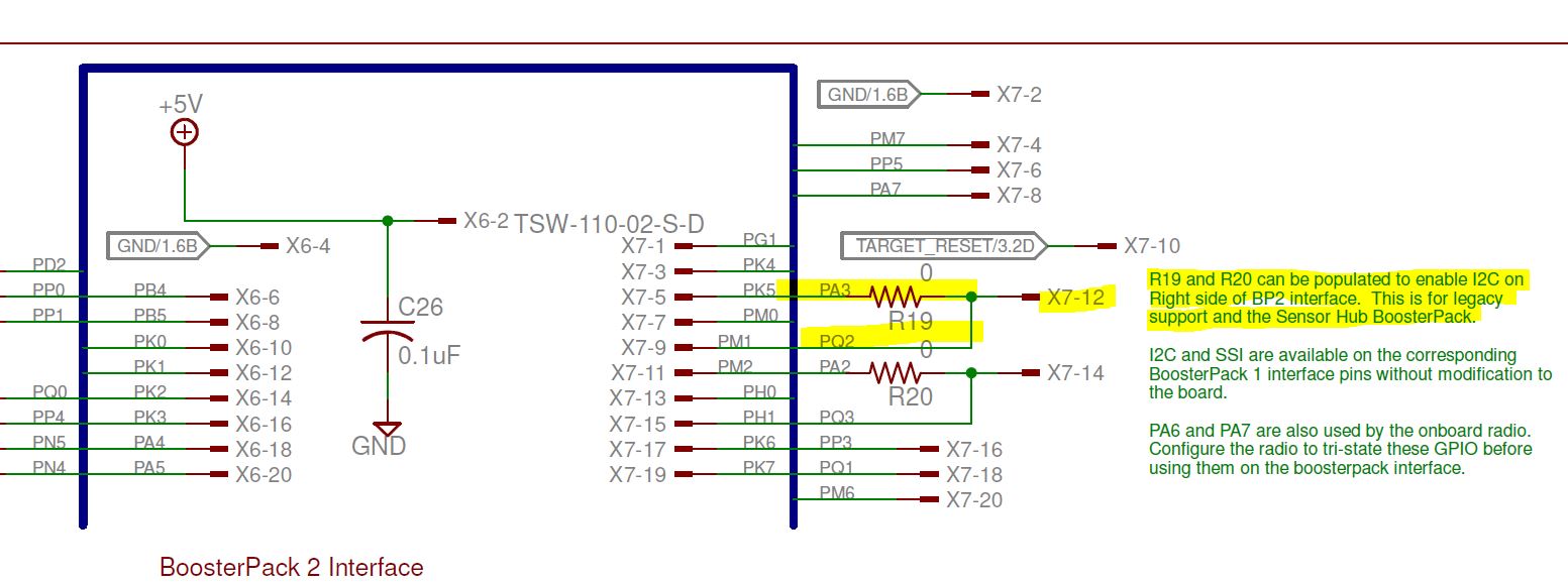
If I send a '1' out on PortA pin 3 (0x08 or 0xEA for instance), PortQ pin 2 apparently is also set!?
And PortQ pin 2 is supposed to be input! Not the case any more, it seems. I have a switch connected to Q2, and the above loop mirrors the state of the switch, until a 1 is written to PortA bit 3.
I have been through all 8 bits on portA one by one. Only when bit 3 is set, I see this.
What am I doing wrong?
Or, what can I do about it?