This thread has been locked.

If you have a related question, please click the "Ask a related question" button in the top right corner. The newly created question will be automatically linked to this question.

EK-TM4C123GXL: USB connection pin to PB1 of TM4C123

Part Number: EK-TM4C123GXL

Sir

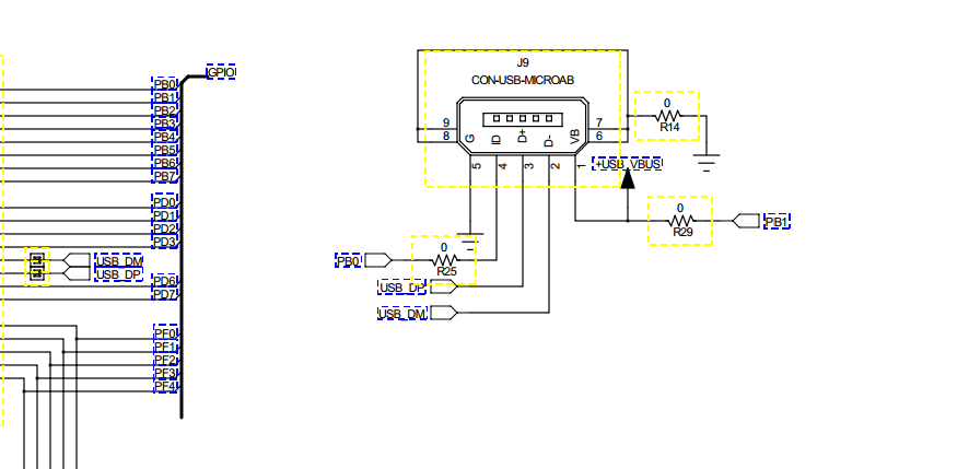
as per the attached photos, we have designed our board with TM4C123 MCU and used the circuit schematics as same as in the development file of  EK-TM4C123GXL,

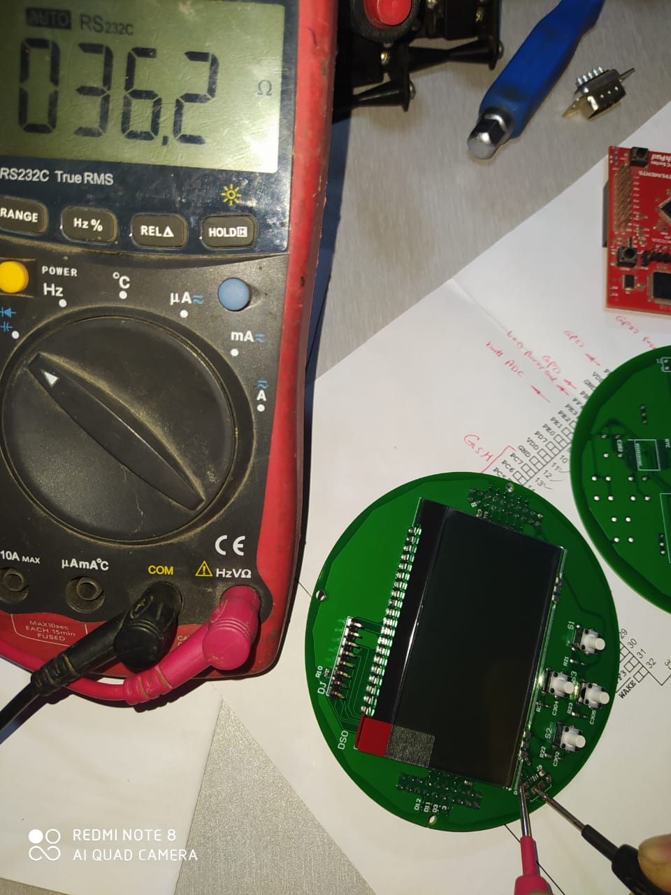
but once we connected the USB port, it caused a damage to some components and made the MCU PB1 is all the time connected to GND of PCB.

we ask you to recommend the right schematics of EK-TM4C123GXL because we discovered that the actual EK-TM4C123GXL PCB is totally different than the manual.

  • Hello Hani,

    What do you mean the PCB is different than manual schematic?

    Perhaps the confusion is that the schematic diagram vs the actual connector is reverse in order of connections from what you expect? The Schematic is laid out where you are looking at the USB plug it self and not the back side with the pins.

    In other words, if you look at the connections on the PCB without removing the USB connector, then you will find Pin 1 for VBUS is closest to the LaunchPad Header pins and Pin 5 for Ground is closest to the Power Select switch.

    Regarding your design, always make sure to follow our design guidelines documentation: https://www.ti.com/lit/pdf/spma059

  • Dear Ralph

    we have used the schematic existing in the below link file, but if you reviewed it with TM4C123GXL PCB , you will see there are a lot of differences, also before we design our PCB we tried to use the EAGLE file of the board but it was corrupted, so if you have a valid file, would you please share it.

    https://www.ti.com/lit/ug/spmu296/spmu296.pdf?ts=1612420843694&ref_url=https%253A%252F%252Fwww.ti.com%252Ftool%252FEK-TM4C123GXL

    Thanks

    Hani

  • Hello Hani,

    Sorry but as someone who works with the EVM daily and has the design files we used to fabricate the board, I respectfully disagree that there are any differences between our provided schematic and the PCB.

    Hani Ahmed said:
    also before we design our PCB we tried to use the EAGLE file of the board but it was corrupted, so if you have a valid file, would you please share it.

    The TI site says Eagle but it was made with Mentor PADS version 9.3 and the files are valid from what I see after downloading.

    Again, I would recommend you check your design against our System Design Guidelines documentation to see what might be the cause.