This thread has been locked.

If you have a related question, please click the "Ask a related question" button in the top right corner. The newly created question will be automatically linked to this question.

TM4C1290NCPDT: Failed to boot 1 out of 1000 power cycle

Part Number: TM4C1290NCPDT

Hello,

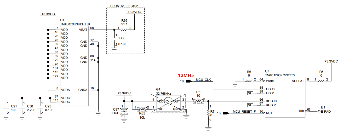
We are using TM4C1290NCPDTT3 in one of our design and the boot image stored in its internal flash memory. Normally it is booting and the application image is running good with no issues. Once in a while it failed to boot and when we simulated power cycle test, observed it failed to boot 10 out 10000 power cycle. When it failed to boot, asserting system reset on the pin-70 (RST) is not doing anything and remains hang. Tried to connect with JTAG via code composure studio and it failed to connect. It requires power cycle to get it back to working. Normally JTAG connections are working good and asserting reset pin, resets the application image running in microcontroller. Not sure what am I missing in the design, appreciate your help to resolve this issue. Not sure is this a known behavior with this controller..?

We are using 13MHz external clock and the reset will be released after 1second from power-ON. The +3.3V voltage looks good with power-up ramp 10uS and 13MHz clock is looking good when the reset is released after 1second from power-ON. This failure is occurring randomly and its happening in all the boards we built (~20-Boards) at both +75'C and -40'C temperature. 

Thanks,

Boopathy

  • Hi Boopathy,

      Are you attaching some image? It is not viewable so please reattach the image again.

      I have some questions:

      - Which TivaWare version are you using?

      - Are you using the TivaWare bootloader example or this is your own bootloader?

      - Can you reproduce the problem on the LaunchPad board?

      - Do you have a 4.7kohm resistor connected between the RBIAS pin and the GND? This is in regard to the Eth#03 errata. 

      - How do you know it is hanging in the bootloader, not the application? 

      - What is your final system clock frequency?

      - My gut feeling is there may be something wrong with the clock. Can you monitor your 13Mhz external clock? Does it look normal at the time of the failure?

      - If you are using a crystal, can you try with a direct 13Mhz clock input instead of the crystal for experiment?


  • Hi Charles,
    Below is the image I tried to attach, seems like it did not loaded properly. We are using our own bootloader and application software. we have certain things enabled in bootloader and they were not happening when it failed to boot. We don't have the LaunchPad board, will give a try in that board once we get them. I dont see any pin with name RBIAS in this controller TM4C1290NCPDTT3. The input 13MHz clock is looking good during the time when reset is released and it is looking good during the failure.


    Thanks,

    Boopathy

  • Hi,

      There is no RBIAS pin in the TM4C1290NCPDT so you can disregard my earlier comment about the RBIAS pin. You are using your own bootloader and I really can't comment if there is any issue with your bootloader or not. Please do two experiments if possible on your end. First, try to run your bootloader and application on the LaunchPad and see if you can reproduce the issue. Second, run the TivaWare provided bootloader along with your application and see if you can reproduce the problem on your custom board. With these two experiments it will give us better ideas on what is going wrong. 

      Are you showing the complete schematic on your power supply. I don't see any decoupling capacitors as recommended by the TM4C129x system design guideline. https://www.ti.com/lit/pdf/spma056.

    3.4.3 Decoupling Capacitors Ideally, Tiva™ C Series microcontrollers should have one decoupling capacitor in close proximity to each power-supply pin. Decoupling capacitors are typically 0.1 μF in value and should be accompanied by a bulk capacitor near the microcontroller. The combined VDD and VDDA bulk capacitance of the microcontroller is typically between 2 μF and 22 μF, with values on the upper end of that range providing measurable ripple reduction in some applications, especially if the circuit board does not have solid power and ground planes. Bulk capacitance is particularly important if the microcontroller is connected to highspeed interfaces or must source significant GPIO current (that is, greater than 4mA) on more than a few pins. For optimal performance, locate one decoupling capacitor adjacent to each VDD power and ground pin pair. At a minimum, there should be one decoupling capacitor on each side of the microcontroller package connected between VDD and Ground